Fluid machine and scroll compressor

a technology of fluid machine and scroll compressor, which is applied in the direction of machines/engines, rotary/oscillating piston pump components, liquid fuel engines, etc., can solve the problems of increasing becoming an obstacle to reducing the size the inevitable increase of the outer dimensions of the fluid machine, so as to reduce the size of the outline shape

Active Publication Date: 2007-12-20
MITSUBISHI HEAVY IND LTD
View PDF4 Cites 14 Cited by
  • Summary
  • Abstract
  • Description
  • Claims
  • Application Information

AI Technical Summary

Benefits of technology

[0027]In consideration of the circumstances described above, an object of the present invention is to provide a fluid machine able to secure a sectional area of a pass

Problems solved by technology

Since the diameter of the housing side is increased to secure the required dimensions for this gap section δ, the outer dimensions of the fluid machine increase by this amount, becoming an obstacle to reducing the size of the fluid machine.
This also results in an inevitable increase in the outer dimensions of the fluid machine.
As a result, the outline shape of the conventional fluid machine is unnecessarily large.
On the other hand, if a ball bearing is used for the main bearing, there will be a problem of an increase in the size of the housing.
However, the gap within the interior of the needle shaped roller bearing having an outer ring is small compared to a ball bearing.
As a result, if the needle shaped roller bearing having an outer ring is used as a main bearing, insufficient refrigerant is introduced into the bearing, raising the possibility of insufficient lubrication for the bearing.
However, since the roller bearing disclosed in Japanese Unexamined Patent Application, Publication No. 2000-2250 needs to use a needle shaped roller bearing having an outer ring in a special

Method used


Image

  • Fluid machine and scroll compressor
  • Fluid machine and scroll compressor
  • Fluid machine and scroll compressor

Examples


first embodiment

[0111]Hereinafter, a first embodiment of a fluid machine according to the present invention is described, with reference to the drawings.

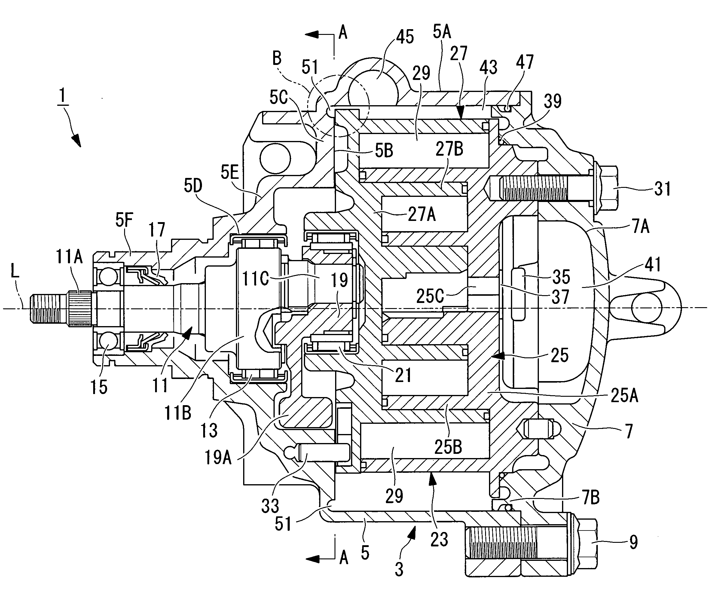
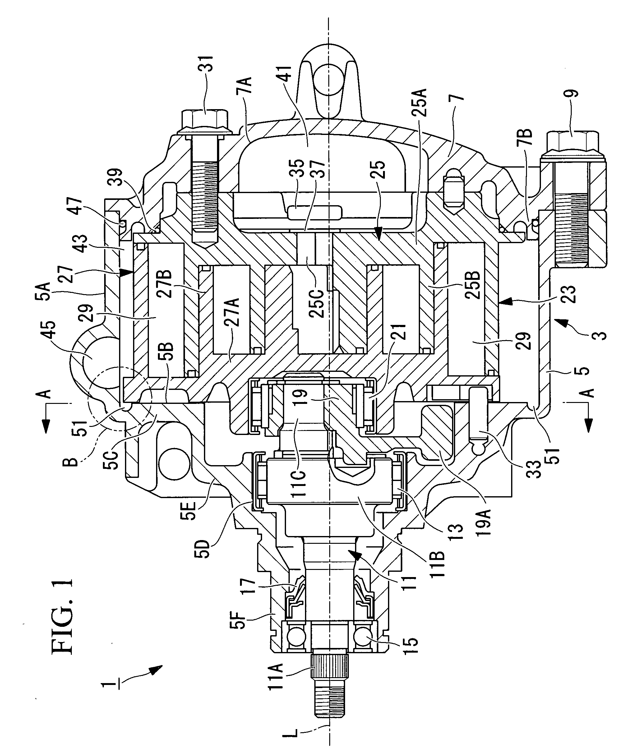
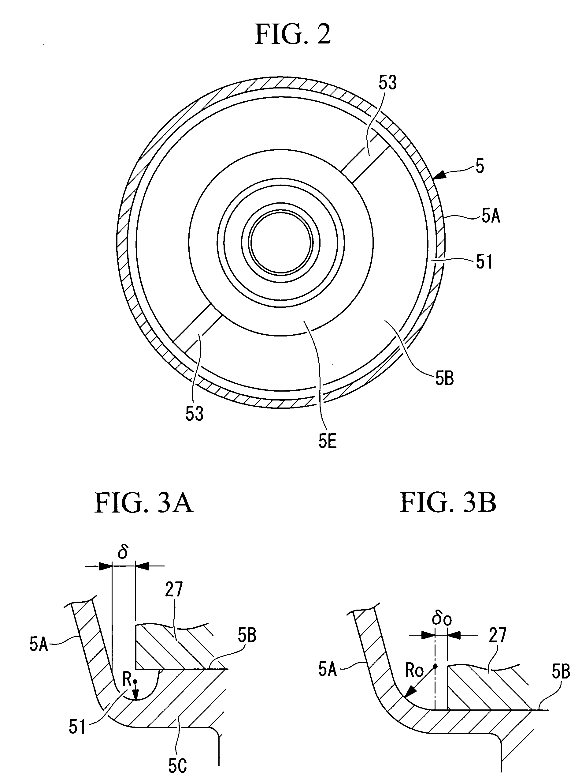
[0112]FIG. 1 is a sectional view showing a scroll compressor 1 used for compression of refrigerant gas or the like, as the first embodiment of the fluid machine according to the present invention.

[0113]The scroll compressor 1 shown in the diagram is a horizontal type applied to a refrigeration apparatus or air conditioning apparatus, in particular, to a refrigeration apparatus or air conditioning apparatus for a vehicle, and has a housing 3 that forms an approximate outline of the scroll compressor 1 and that houses a compression mechanism in its inside space. This housing 3 is provided with a low pressure side front housing 5 and a high pressure side rear housing 7, respective flange sections of which being integrally tightly fastened to each other and fixed by bolts 9 only one shown. Moreover, the compression mechanism of the scroll compressor 1 ...

second embodiment

[0140]Hereinafter, a second embodiment of the present invention is described, with reference to FIG. 4 and FIG. 5. A scroll compressor 101 according to the present embodiment is used for compression of refrigeration gas (fluid) of an air conditioning apparatus for example.

[0141]FIG. 4 is a sectional view for explaining a construction of the scroll compressor 101 according to the present embodiment. FIG. 5 is a cutaway sectional view showing one part of a large diameter shaft section.

[0142]The scroll compressor 101 is provided with a housing 103, a scroll compression mechanism (compression mechanism) 105, a rotation prevention section 107, and a crankshaft 109.

[0143]The housing 103 is a hermetic container within which the scroll compression mechanism 105 and so forth are arranged as shown in FIG. 4.

[0144]The housing 103 is provided with a rear case 111 that constitutes a rear section (upper side in FIG. 4) and a front case 113 that constitutes a front section (lower section in FIG. 4...

third embodiment

[0209]Hereinafter, a third embodiment of the present invention is described, with reference to FIG. 9 through FIG. 11.

[0210]FIG. 9 is a longitudinal sectional view showing a scroll compressor 201 according to a third embodiment of the present invention.

[0211]The scroll compressor 201 has a housing 203 that constructs an outline thereof. This housing 203 is constructed by integrally fastening and fixing a front housing 205 and a rear housing 207 by bolts 209 (second bolts). Flanges 205A and 207A for fastening are integrally formed at equal intervals in a plurality of places, for example in four places, on each of the circumferences of the front housing 205 and the rear housing 207. By fastening these flanges 205A and 207A to one another using the bolts 209, the front housing 205 and the rear housing 207 are integrally joined.

[0212]A crankshaft 211 is supported within the front housing 205 via a main bearing 213 and a sub bearing 215, allowing it to rotate freely around the axis L. On...


PUM


Abstract

There is provided a fluid machine able to secure a sectional area of a passage sufficient for gaseous fluid flow from a suction port to a compression mechanism, while able at the same time to achieve a reduction in size of the outline shape. In a scroll compressor where a scroll compression mechanism 23 is housed within a housing 3 having a funnel shaped, a compression mechanism main body of the scroll compression mechanism 23 is arranged in a wide opening section of a front housing 5, and a compression mechanism driving section is arranged in a narrow section, a concave section 51 is formed on the outside of a thrust receiving surface 5B which is positioned on a bottom surface of the wide opening section and which supports the compression mechanism.

Description

BACKGROUND OF THE INVENTION[0001]1. Field of the Invention[0002]The present invention relates to a fluid machine such as a scroll compressor, in particular, to a scroll compressor applied to a refrigerant compressor for a refrigeration apparatus or an air conditioning apparatus.[0003]This application is based on Japanese Patent Application Nos. 2006-164677, 2006-167903, and 2006-173897, the content of which is incorporated herein by reference.[0004]2. Description of Related Art[0005]Conventionally, a fluid machine such as a scroll compressor that compresses gaseous fluid is commonly known.[0006]As an example of this kind of fluid machine, there is a fluid machine that is provided with a funnel-shaped lower pressure side housing having a suction port for introducing low pressure gaseous fluid, and a high pressure side housing having a discharge opening for discharging high pressure gaseous fluid, both housings being integrally connected to form a sealed housing in which a compression...

Claims


Application Information

Patent Timeline
IPC IPC(8): F01C1/04
CPCF01C21/02F01C21/10F04C2240/30F04C29/0057F04C2230/21F04C18/0215F16C2360/42A45F5/021A45F2200/0516
Inventor FUJITA, KATSUHIROMORO, TOMOHISAKUWAHARA, TAKAYUKIWATANABE, KAZUHIDEUKAI, TETSUZOUHIOKI, NORIOYAMAZAKI, HIROSHITAKEUCHI, MAKOTOHIMENO, TAKAMITSU
Owner MITSUBISHI HEAVY IND LTD
Why Eureka
Try Eureka