Method for measuring channel quality and base station in mobile communications system

a mobile communications system and channel quality technology, applied in the field of mobile communications systems, can solve the problems of large overhead, inability to efficiently allocate pilot resources, and inability to efficiently allocate pilot resources, and achieve the effect of small overhead and efficient channel quality measuremen

Inactive Publication Date: 2007-12-20
NEC CORP
View PDF4 Cites 116 Cited by
  • Summary
  • Abstract
  • Description
  • Claims
  • Application Information

AI Technical Summary

Benefits of technology

[0014] An object of the present invention is to provide a mobile communications system, a channel quality measurement method, and a base station that enable efficient measurement of the channel quality of each mobile station.
[0016] As described above, according to the present invention, the pilot resource specific to channel quality measurement is not prepared for every mobile station. In a frequency block in which channel quality measurement is possible using a demodulation pilot signal, the demodulation pilot signal is used to measure the channel quality. In a frequency block in which the demodulation pilot signal is not transmitted, the pilot signal specific to channel quality measurement is transmitted to measure the channel quality. Thus, it is possible to achieve efficient channel quality measurement, with the small overhead across the whole bandwidth composed of a plurality of frequency blocks.

Problems solved by technology

However, according to the above-described method, the pilot resource cannot be efficiently allocated, as will be described below.
As a result, resource allocation techniques as shown in FIG. 2A have had the problem that the overhead is large and the pilot resource cannot be efficiently allocated.
Due to this limit, the problem also arises that the number of mobile stations for which the base station performs CQI measurement becomes smaller when a pilot signal is used both for demodulation and CQI measurement.

Method used


Image

  • Method for measuring channel quality and base station in mobile communications system
  • Method for measuring channel quality and base station in mobile communications system
  • Method for measuring channel quality and base station in mobile communications system

Examples


first exemplary embodiment

1. First Exemplary Embodiment

1.1) Resource Allocation

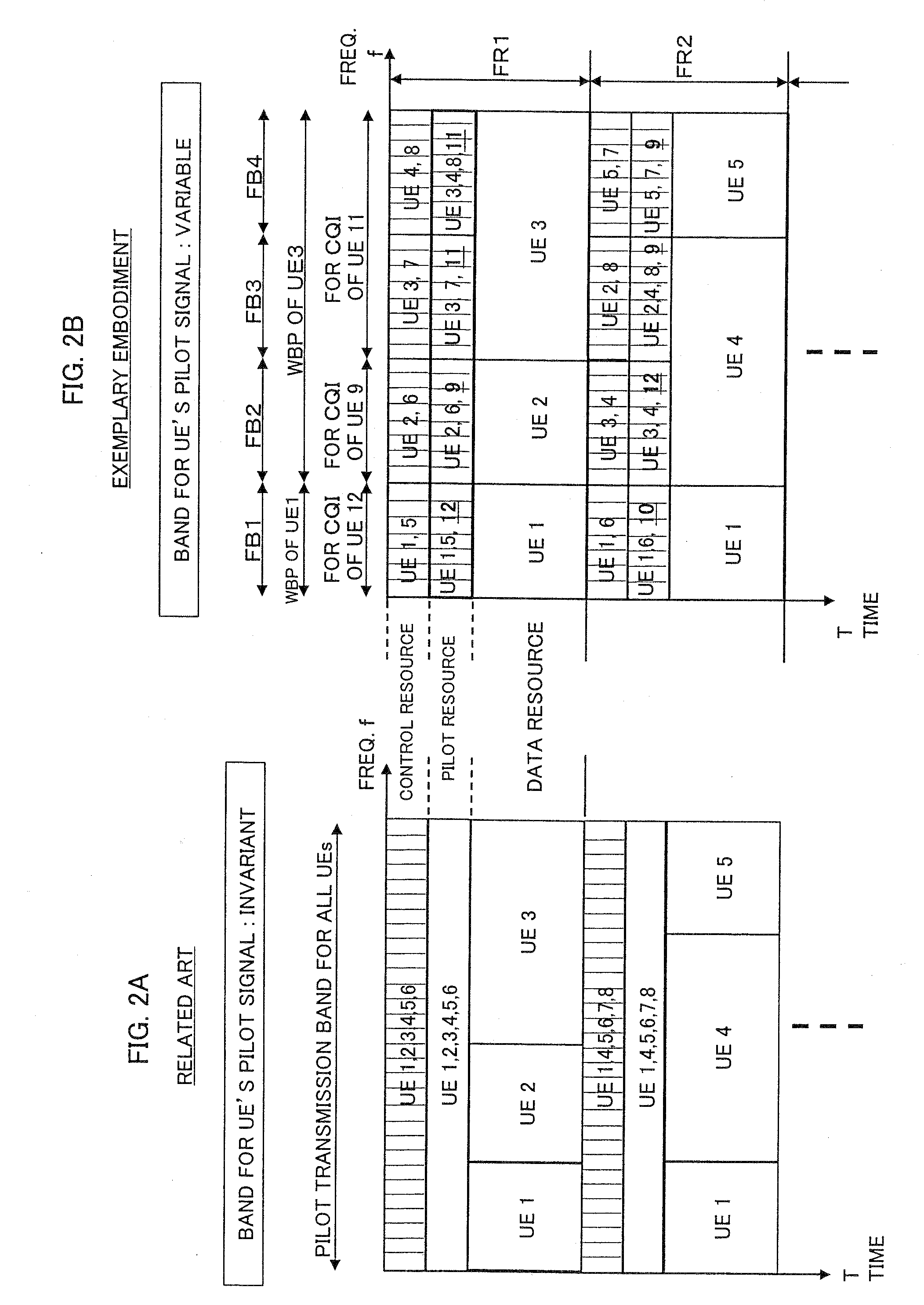
[0039]FIG. 2B is a diagram schematically showing the allocation of a resource for channel quality measurement according to a first exemplary embodiment of the present invention. In this exemplary embodiment, a control signal, pilot signal (also referred to as reference signal), and data signal are time-division-multiplexed (TDM) in each frame (also referred to as sub-frame). The resources to be allocated in one frame FR, in each frequency block FB, are referred to as a control resource, a pilot resource, and a data resource. Note that a control signal in this example is an uplink control signal regarding a downlink data signal (called data non-associated control signaling) and contains a downlink CQI, ACK / NACK indicating whether or not downlink packets have been correctly received, or the like.

[0040] In addition, four frequency bands (frequency blocks FB1 to FB4) are illustrated here to simplify the description. However, the nu...

second exemplary embodiment

2. Second Exemplary Embodiment

[0099]FIG. 11 is a block diagram showing configurations of a base station and mobile station in a mobile communications system according to a second exemplary embodiment of the present invention. However, since the configuration of a base station 100 is substantially the same as that of the base station according to the first exemplary embodiment shown in FIG. 3, the same reference numerals as in the first exemplary embodiment will be used, and the detailed description thereof will be omitted. Moreover, the configuration of a mobile station 200 also is basically the same as that of the mobile station according to the first exemplary embodiment shown in FIG. 7, except that a transmission mode selection section 207 is provided in the second exemplary embodiment. Therefore, the same reference numerals as in the first exemplary embodiment are given to the blocks having the same functions as the counterparts in the first exemplary embodiment shown in FIG. 7,...

first example

2.1.1) First Example

[0104]FIG. 13 is a flow chart showing a first example of the process in the step S320 in FIG. 12. First, the scheduler 103 determines whether or not the CQI-specific pilot resource can be allocated (step S321). If it can be allocated (step S321: YES), the control goes back to the step S311 in FIG. 12, where the allocation of the CQI-specific pilot resource is carried out (step S311). Thereafter, the processing in the above-described step S312 and subsequent steps is carried out.

[0105] If it is impossible to allocate the CQI-specific pilot resource because of the insufficient resource or the like (step S321: NO), the scheduler 103 controls the control signal generation section 106 to have it generate a downlink control signal indicating that the CQI-specific pilot resource is not allocated, transmits the downlink control signal to the mobile station 200 (step S322), and then waits for a response from the mobile station 200. The downlink control signal here is tra...


PUM


Abstract

A channel quality measurement method that accomplishes efficient channel quality measurement for each mobile station is presented. In a frequency band including a plurality of frequency blocks, a base station measures the channel quality of each of a plurality of mobile stations. With respect to each mobile station, when a pilot resource for demodulation is not allocated in at least one of the frequency blocks, the base station allocates a specific pilot resource for channel quality measurement in that frequency block. The channel quality of each mobile station in the plurality of frequency blocks is measured by using one or both of the pilot resource for demodulation and the dedicated pilot resource for channel quality measurement.

Description

BACKGROUND OF THE INVENTION [0001] 1. Field of the Invention [0002] This application is based upon and claims the benefit of priority from Japanese Patent Application No. 2006-168476, filed on Jun. 19, 2006, the disclosure of which is incorporated herein in its entirety by reference. [0003] The present invention relates to a mobile communications system and, more particularly, to techniques for measuring the channel quality of each mobile station, pilot-resource allocating techniques, and a base station using these techniques. [0004] 2. Description of the Related Art [0005] A base station in a mobile communications system performs resource scheduling to enhance the efficiency of radio resources. The scheduling methods can be classified into two broad types; one is channel-independent scheduling by which a resource is allocated periodically, for example by round-robin, irrespective of channel quality; the other one is channel-dependent scheduling by which, taking channel quality into...

Claims


Application Information

Patent Timeline
Patent Type & Authority Applications(United States)
IPC IPC(8): H04Q7/20H04W24/10H04W72/08
CPCH04L1/0026H04L1/20H04W72/085H04W24/10H04L5/0048H04W72/542H04B17/101
Inventor INOUE, TAKAMICHIKAKURA, YOSHIKAZU
Owner NEC CORP
Why Eureka
Try Eureka