Method of breaking chips and apparatus therefor

a technology of metal cutting and chip breaking, which is applied in the direction of shaping cutters, auxiliary equipment, manufacturing tools, etc., can solve the problems of unpredictable jams, chip disposal and quality control of machined workpiece surfaces, and serious difficulties in operational safety, so as to reduce the force acting on the cutting edge of machined workpieces, reduce temperature, and ensure the effect of operation safety

Inactive Publication Date: 2000-02-22
NAT UNIV OF SINGAPORE
View PDF18 Cites 20 Cited by
  • Summary
  • Abstract
  • Description
  • Claims
  • Application Information

AI Technical Summary

Benefits of technology

The chip breaker of the described embodiments of the present invention breaks the chips generated during metal cutting processes including turning, facing, boring, parting and other metal cutting processes in which chip breaking is required, at most combinations of machining conditions including the workpiece material properties, cooling conditions, cutting speed, feed rate and depth of cut, into small pieces in forms of less than one circle of small radius. The chip breaker guides the broken chips to drop gently from the tool main flank to the container of the machine, such that the operational safety, machined workpiece surface quality and chip disposal efficiency are ensured. The chip breaker reduces the force acting on the tool cutting edge by sharing the force acting on the tool rake face, reduces temperature at the tool cutting region by reducing cutting force at the tool rake face and by breaking the chips frequently, and consequently reduces the tool wear rate and increases the tool life. The chip breaker works with inserts of all kinds of shapes and obviates the need for geometries constructed on the tool inserts for chip breaking purposes, such that the cost on tool inserts can be substantially reduced by using flat rake face inserts rather than inserts with complicated geometry at the rake face. The breaker may be constructed with the tool insert, in which the chip breaker body is formed on the tool rake face.

Problems solved by technology

Such continuous chips cause serious difficulties in operational safety, chip disposal and quality control of the machined workpiece surface.
More seriously, continuous chips can cause unpredictable jams in the cutting process, which prevent automation of machining systems.
These chip breakers do not make sure that the chip is broken during cutting and chip breaking can be achieved only in some machining conditions.
It is very difficult to predict whether the chip will be broken by these chip breakers from a set of given machining conditions, that is, when these chip breakers are used in metal cutting, it is uncertain that the chip will break.
Further, when chips are broken by such chip breakers, the chips usually fly in many directions and these still cause difficulties in operational safety, control of machined workpiece surface quality and chip disposal.
Furthermore, some of these chip breakers weaken the tool cutting edge and consequently shorten the tool life.

Method used


Image

  • Method of breaking chips and apparatus therefor
  • Method of breaking chips and apparatus therefor
  • Method of breaking chips and apparatus therefor

Examples


first embodiment

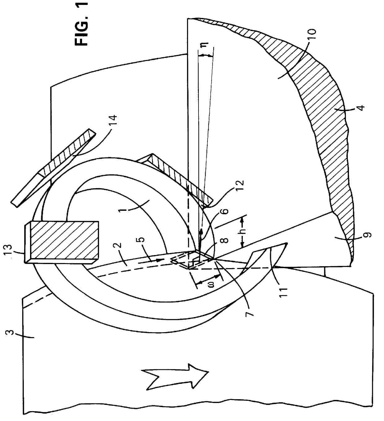
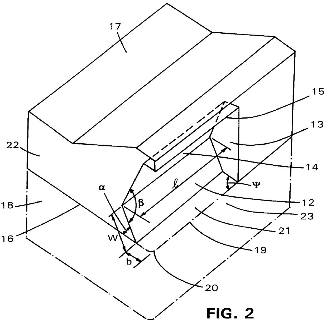
FIG. 2 shows the chip breaker for turning processes. The chip breaker 22 is clamped together with the tool insert 18 on a tool holder. The bottom face 16 of the chip breaker is in contact with the rake face 21 of the tool insert. The clamping face 17 of the chip breaker is in contact with the clamp of the tool holder (not shown). The chip breaking body of the chip breaker is adjacent to the main cutting edge 19, and comprises a pivoting plane 12 which is inclined to the tool rake face 21, a side-flow restricting plane 13 which is approximately perpendicular to cutting edge 19, an up-curl guiding plane 14 and a supplementary reaction plane 15. During cutting, the chip grows from the shear plane and flows along the tool rake face 21 towards plane 12 of the chip breaker, with an up-curl caused by friction and thermal expansion at the tool-chip interface and a side-curl caused by differences in the material flow velocities along the main cutting edge 19 and tool nose 20. Once the head o...

second embodiment

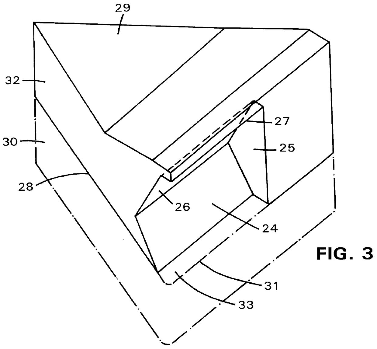
FIG. 3 shows the chip breaker of the present invention, for turning with a triangular tool insert 30. The bottom face 28 of the chip breaker 32 is in contact with the tool rake face 33. The clamping face 29 of the chip breaker is in contact with the clamp of the tool holder (not shown). The chip breaking body of the chip breaker is the same as that of the embodiment shown in FIG. 2, which comprises a pivoting plane 24, a side-flow restricting plane 25, an up-curl guiding plane 26 and a supplementary pivoting plane 27. The chip breaking mechanism of this embodiment is the same as the one shown in FIG. 2.

Compared the embodiments of the chip breaker shown in FIGS. 2 and 3, it can be seen that embodiments in different shapes of the chip breaker can be constructed according to the present invention, which suit the shape of the tool inserts used but share the same chip breaking body.

FIG. 4 shows another embodiment of the chip breaker of the present invention, for facing or boring processe...

fifth embodiment

From the above descriptions of embodiments of the chip breaker, it can be seen that the dimensional values of the chip breaking body in the chip breaker can be varied within a range without losing effectiveness in chip breaking. However, the shape of the broken chip might vary with the ratio of the depth of cut to the distance from the tool nose 20 to the side-flow restriciting plane 13 as shown in FIG. 2, and the radius of the chip curl might vary with the ratio of the feed rate to the distance from the tool main cutting edge 19 to the pivoting plane 12 as shown in FIG. 2. Therefore, in one preferred form, the dimensional values of the chip breaking body may be adjustable. FIG. 6 shows the chip breaker of the present invention, with the chip breaking body being adjustable. The clamping surface 57 of the chip breaker 64 is in contact with the clamp of the tool holder. The chip breaking body is formed by an adjustable body 68 comprising a first surface forming a pivoting plane 52 and...


PUM

PropertyMeasurementUnit
chip side-flow angleaaaaaaaaaa
angleaaaaaaaaaa
widthaaaaaaaaaa

Abstract

A method of breaking chips is disclosed in which the chip generated during cutting is broken into small pieces by increasing the shear strain at the shear plane, which is the joint between the chip and the workpiece, until fracture occurs at the shear plane. This is achieved by forming the chip (1) generated during cutting into a lever, in which the head (11) of the chip is the load-lifting point receiving a force from a first plane (9), the contact between the chip (1) and a second plane (12) of the chip breaker is the fulcrum, and the root (8) of the chip, which joins the chip to the shear plane, is the force-exerting point exerting a force additional to the shear force acting along the shear plane to strain the material until fracture occurs at the shear plane.

Description

This invention relates to a method of breaking chips in metal cutting and a chip breaker for use in the method.In metal cutting, particularly in lathing of ductile materials, continuous chips are usually generated. Such continuous chips cause serious difficulties in operational safety, chip disposal and quality control of the machined workpiece surface. More seriously, continuous chips can cause unpredictable jams in the cutting process, which prevent automation of machining systems. Therefore, in metal cutting it is strongly desired to have the chips generated in discontinuous forms. Chip breakers for metal cutting processes are devices used for breaking chips into small pieces. Two types of chip breakers have been proposed in the prior art--obstruction devices separate from a tool insert, and combinations of grooves and obstacles formed on the rake face of the tool insert. During metal cutting processes, such chip breakers work to bend the chip after it has been generated. These c...

Claims


Application Information

Patent Timeline
Patent Type & Authority Patents(United States)
IPC IPC(8): B23B25/00B23B25/02
CPCB23B25/02Y10T407/11Y10T82/10Y10T407/114Y10T407/137Y10T407/24
Inventor LI, XIAO PING
Owner NAT UNIV OF SINGAPORE
Why Eureka
Try Eureka