
Systems and methods for implantable leadless bone stimulation

a leadless bone and implantable technology, applied in the field of electric stimulation treatments, can solve the problems of patients not keeping batteries charged, the electrode may or may not be removed, and the compliance of noninvasive ebgs and ubgs is often an issue, so as to enhance bone growth, promote healing, and enhance bone healing

Active Publication Date: 2007-12-20
EBR SYST
View PDF18 Cites 69 Cited by
  • Summary
  • Abstract
  • Description
  • Claims
  • Application Information

AI Technical Summary

Benefits of technology

This patent describes a system for using electrical stimulation to promote bone growth and fusion. The system includes a controller-transmitter that sends vibrational energy to a receiver-stimulator that is either implanted or in close proximity to the bone. The stimulation electrodes would be in direct contact or close proximity to the bone or the associated devices used for bone fusion or repair. The system can also simultaneously provide ultrasonic bone treatment and electrical stimulation to enhance bone growth and healing. The technical effects of this system include accelerated bone healing, improved bone growth and fusion, and enhanced therapy relative to either technique alone.

Problems solved by technology

Although the current generator is removed in a second surgical procedure when stimulation is completed, the electrode may or may not be removed.
Compliance with noninvasive EBGS and UBGS is often an issue because it requires the patient to apply the therapy at a prescribed regimen and intensity.
Patients may not keep batteries charged, may not comply with instructions, may fail to wear electrodes for required durations, or may adjust intensities inappropriately for the electrical bone stimulation therapy or ultrasound therapy application to be effective.
Both the metatarsals and scaphoid bones are at a relatively high risk of nonunion after a fracture.
However, at a cellular level, both bone types are composed of lamellar bone and cannot be distinguished microscopically.
Such implanted electrode / lead wires exhibit significant problems, such as infection, lead failure, and electrode / lead dislodgement.

Method used


Image

  • Systems and methods for implantable leadless bone stimulation
  • Systems and methods for implantable leadless bone stimulation
  • Systems and methods for implantable leadless bone stimulation

Examples


Embodiment Construction

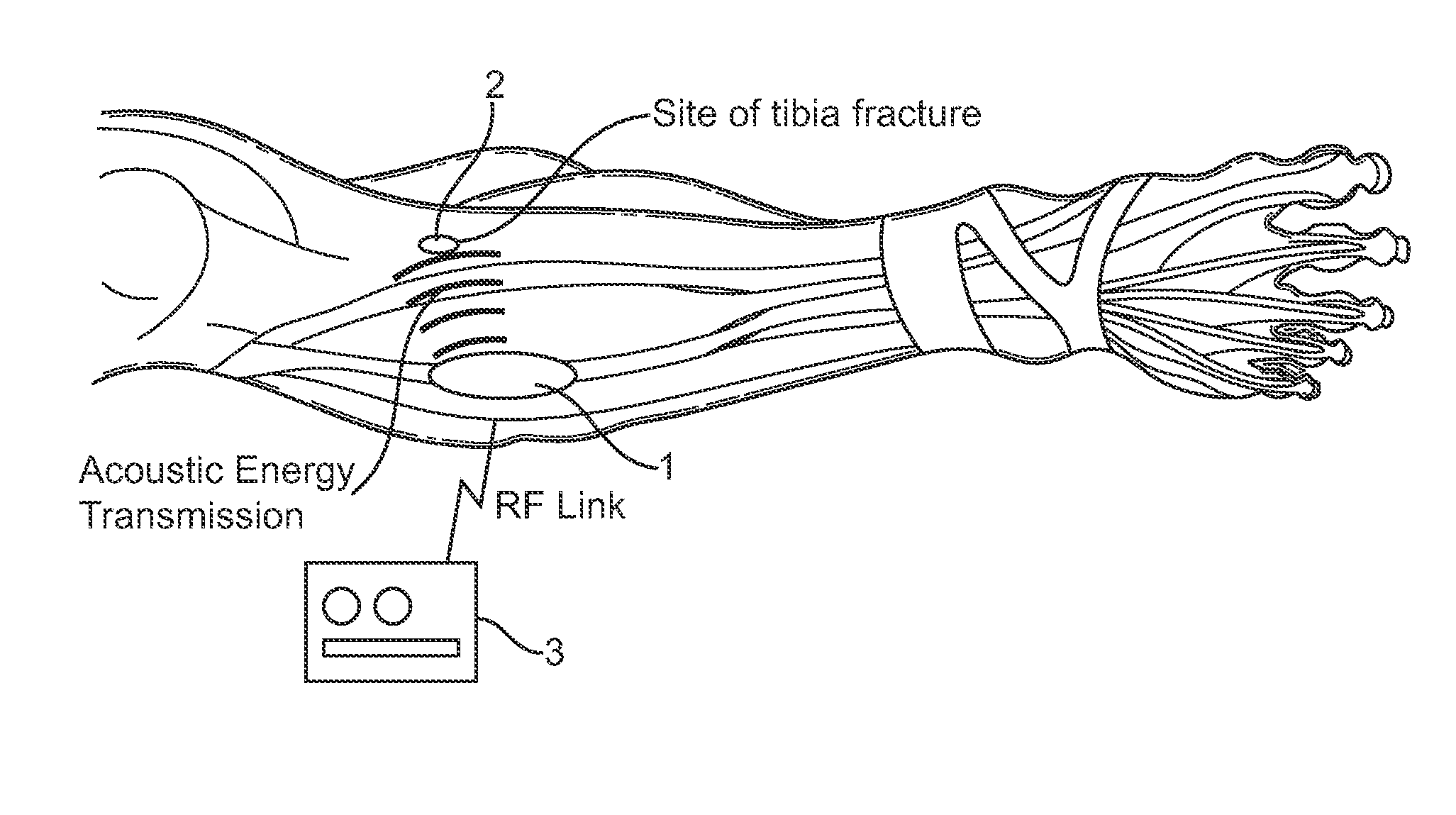
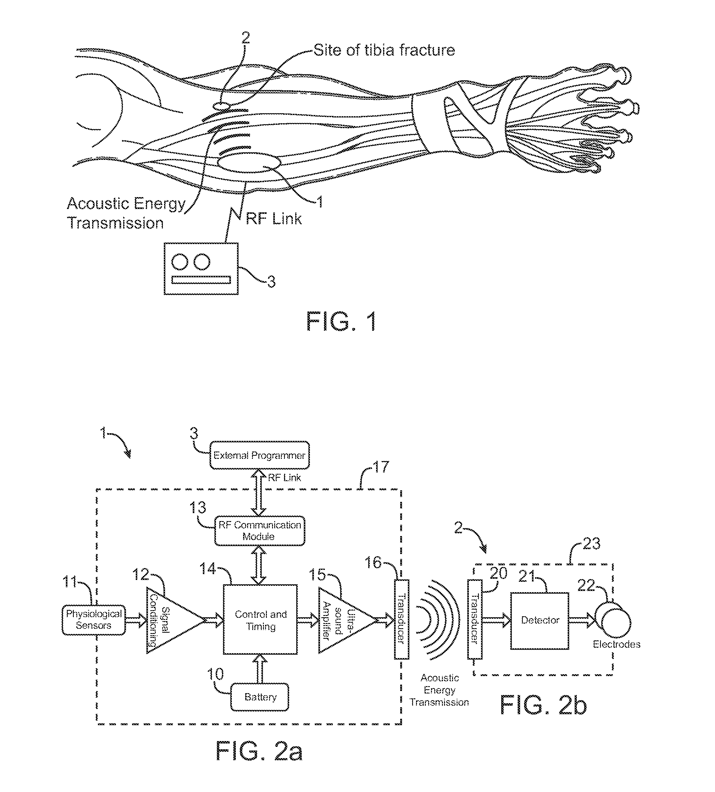
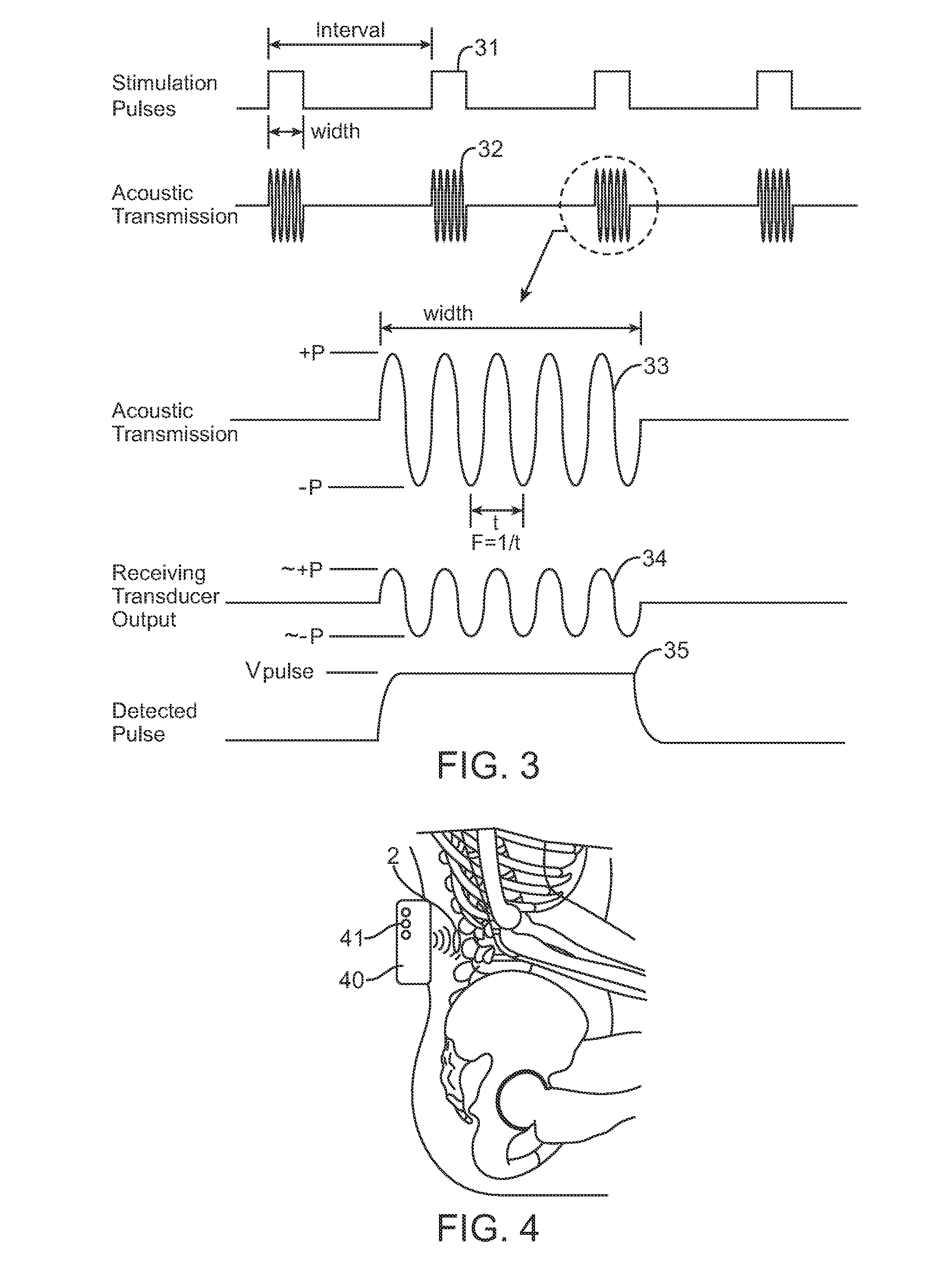
[0026]The systems and devices described here comprise a controller-transmitter device that will deliver vibrational energy and information to one or more implanted receiver-stimulator device(s) that will convert the vibrational energy to electrical energy of a form that can be used to electrically stimulate bone. The vibrational energy can be applied with ultrasound as a single burst or as multiple bursts or as a continuous wave with appropriate selection of the following parameters:

ParameterValue RangeUltrasound frequency20 kHz-10 MHzBurst Length (#cycles)3-continuousStimulation Pulse Duration0.1 μsec-continuousDuty Cycle0-100%Mechanical Index

[0027]The controller-transmitter device contains one or more ultrasound transducers of appropriate size(s) and aperture(s) to generate sufficient acoustic power to achieve the desired stimulation at the location of an implanted receiver-stimulator device. Additionally, multiple implanted receiver-stimulator devices may be placed within the reg...


PUM


Abstract

Systems and methods are disclosed to enhance bone growth by stimulating bone sites for bone regrowth, fusion, or grafts. The invention uses electrical stimulation of the bone site, where vibrational energy from a source is received by an implanted device and converted to electrical energy and the converted electrical energy is used by implanted electrodes to stimulate the bone site. The vibrational energy is generated by a controller-transmitter, which could be located either externally or implanted. The vibrational energy is received by a receiver-transmitter, which could be incorporated into an orthopedic device, such as pin, cage, plate or prosthetic joint used for bone healing.

Description

CROSS-REFERENCES TO RELATED APPLICATIONS[0001]The present application claims the benefit of provisional U.S. Application No. 60 / 805,314 (Attorney Docket No. 021834-001510US), filed Jun. 20, 2006, the full disclosure of which is incorporated herein by reference.BACKGROUND OF THE INVENTION[0002]1. Field of the Invention[0003]The systems and methods of this invention relate to electrical stimulation treatments to enhance bone growth and fusion of bones using implantable devices. Specifically, the present invention relates to systems and methods for providing such stimulation without the use of conventional lead / electrode systems.[0004]2. Description of the Background Art[0005]Electrical stimulation of body tissues is used throughout medicine for treatment of both chronic and acute conditions. One such therapeutic application is using electrical stimulation to increase the rate of bone regrowth, repair, fusion of bones or bone grafts. Commonly implanted devices utilizing electrical stim...

Claims


Application Information

Patent Timeline
Patent Type & Authority Applications(United States)
IPC IPC(8): A61N1/36
CPCA61N1/326A61N1/36035A61N1/36A61N1/37288A61N1/3756A61N1/37217A61N1/36038A61N1/3604A61N1/36007A61N1/36021A61N1/36071A61N1/3787
Inventor COWAN, MARK W.RILEY, RICHARD E.BRISKEN, AXEL F.ECHT, DEBRA S.
Owner EBR SYST
Learn More