Joint revision implant

a backing implant and joint technology, applied in the field of joint revision implants, can solve the problems of reducing the ability to work, voids may remain between the back surface of the implant and the pelvis, and loss of bone stock, so as to encourage bone apposition and promote biological attachment to the implan

Active Publication Date: 2013-02-12
WARSAW ORTHOPEDIC INC
View PDF296 Cites 17 Cited by
  • Summary
  • Abstract
  • Description
  • Claims
  • Application Information

AI Technical Summary

Benefits of technology

[0014]An osteoconductive backing implant for joint revisions is provided that may enhance bone healing and, for cementless implants, bony integration of the implant.

Problems solved by technology

A failed prosthesis and / or dislocation of a total hip replacement generally causes pain, reduces the ability to work, and necessitates a revision operation.
Prosthesis failure and / or dislocations can result from a variety of causes, such as soft tissue laxity, loosening of the implant, and impingement of the femoral neck with either the rim of an acetabular cup implant or the soft tissue or bone surrounding the implant.
Loosening of the implant is often due to bone loss around the implant, caused by adverse tissue reactions to wear particles.
Revision arthroplasty involves additional challenges over primary joint replacement because, in addition to placement of the revision implant, the primary implant must be removed.
A common problem with revision arthroplasty is a loss of bone stock associated with the removal of bone cement, or osteolysis due to wear debris and the body's reaction to it, or from stress shielding, or a combination of these.
Further, in some instances, upon insertion into the acetabulum of an implant, voids may remain between the back surface of the implant and the pelvic bone remaining in the acetabulum.
It has more recently been determined that a stiff backing causes two problems: It generates higher stress peaks around the acetabular rim than those caused by full polyethylene cups, and it reduces the stresses transferred to the dome of the acetabulum, causing stress shielding.

Method used


Image

  • Joint revision implant
  • Joint revision implant
  • Joint revision implant

Examples


first embodiment

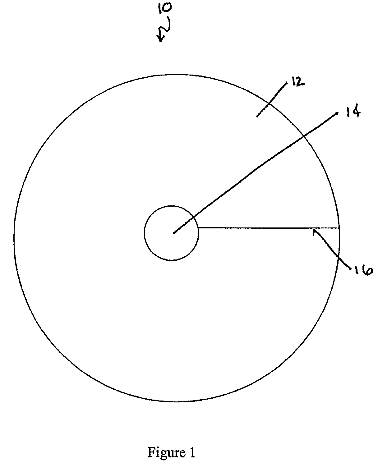
[0043]In a first embodiment, shown in FIG. 1, the backing implant 10 comprises a generally circular sheet 12 having a hole 14. The size, shape, and placement of the hole may be varied. For example, the hole may be centered or may be eccentric, may be circular or may be ovoid, etc. The size, shape, and placement of the hole may be determined based on, for example, concavity of the joint surface. In some embodiments, the hole facilitates folding or shaping the backing implant into a cone, described below. In these embodiments, the hole is sized for such use, generally reducing material that may need to be trimmed at the point of the cone and reducing the likelihood of the backing implant wrinkling during folding. In the figures, the generally circular sheet 12 and the center hole 14 are depicted as being round. It is to be understood, however, that, for the embodiment of FIG. 1 as well as all other embodiments described herein, any suitable geometry may be used for the sheet 12, the h...

second embodiment

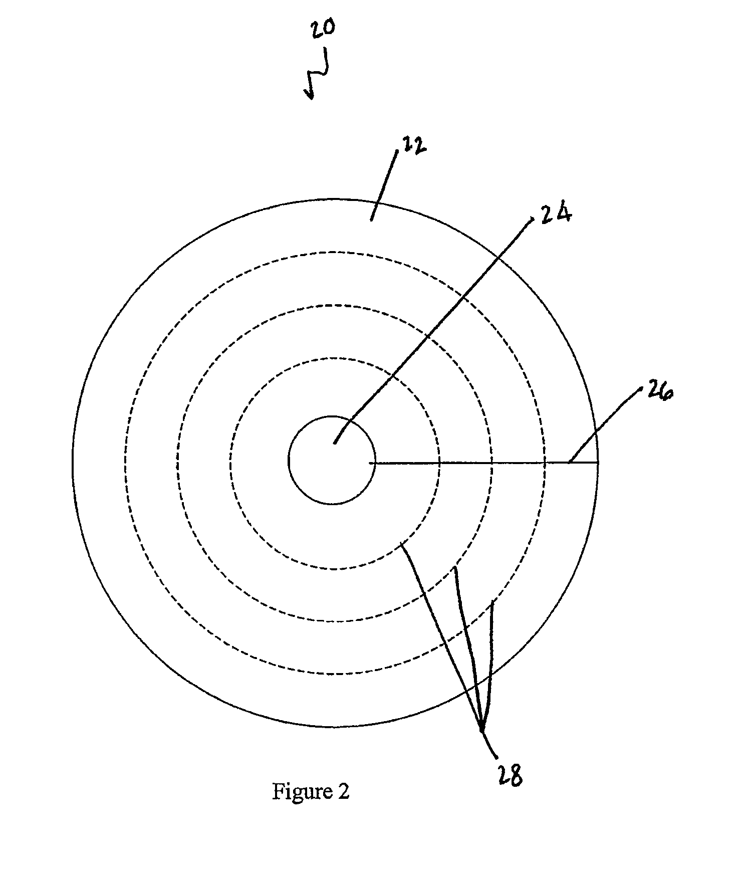
[0044]In a second embodiment, shown in FIG. 2, the backing implant 20 comprises a generally circular sheet 22 having a hole 24 and a slit 26 extending from the hole to the outer edge, as in the embodiment of FIG. 1. The slit 26 may be perforated or may be cut through. The backing implant 20 of FIG. 2 further includes a series of generally concentric perforations 28. The surgeon may select one of the generally concentric perforations 28 corresponding to a desired outer diameter of the generally circular sheet 22. The surgeon then may tear or cut along the generally concentric perforation 28, removing material between the generally concentric perforation 28 and the outer edge, thereby forming an implant of desired size. As with the embodiment of FIG. 1, the surgeon may then fold the sheet 22 into a cone shape. Further, the overlapping edges may be cut and removed. While the generally concentric perforations 28 are depicted as being round, it is to be understood that any desired geomet...


PUM

PropertyMeasurementUnit
inner diameteraaaaaaaaaa
outer diametersaaaaaaaaaa

Abstract

An osteoconductive backing implant for joint revisions is provided that may enhance bone healing and, for cementless implants, bony integration of the implant. The backing implant comprises a generally planar surface that may be formed into a generally hemispherical shape. In one embodiment, the backing implant comprises a disc having an inner hole and an outer edge, at least one slit extending from the inner hole to the outer edge. The disc may be formed from a coherent mass of elongate, mechanically entangled demineralized bone particles.

Description

[0001]This application is a National Stage under 35 U.S.C. 371 of PCT Application No. PCT / US2008 / 053588, filed on Feb. 11, 2008, which claims priority to U.S. Application No. 60 / 889,437, filed Feb. 12, 2007, and to U.S. Application No. 60 / 985,859, filed Nov. 6, 2007, all of which are incorporated herein by reference.FIELD[0002]A backing implant for joint revisions is provided. More specifically, an osteoconductive backing implant for joint revisions is provided.BACKGROUND[0003]Overview of Bone Grafts[0004]The rapid and effective repair of bone defects caused by injury, disease, wounds, or surgery has long been a goal of orthopaedic surgery. Toward this end, a number of compositions and materials have been used or proposed for use in the repair of bone defects. The biological, physical, and mechanical properties of the compositions and materials are among the major factors influencing their suitability and performance in various orthopaedic applications.[0005]Much effort has been inv...

Claims


Application Information

Patent Timeline
Patent Type & Authority Patents(United States)
IPC IPC(8): A61F2/28
CPCA61F2/30721A61F2/30723A61L27/3608A61L27/3641A61L27/3645A61B17/8808A61F2310/00359A61F2/2846A61F2/34A61F2002/2817A61F2002/2835A61F2002/30062A61F2002/30118A61F2002/30121A61F2002/30171A61F2002/30179A61F2002/3021A61F2002/30217A61F2002/30225A61F2002/30561A61F2002/30594A61F2002/30596A61F2002/30616A61F2002/30677A61F2002/3069A61F2002/30736A61F2002/30772A61F2002/3096A61F2002/4631A61F2210/0004A61F2230/0006A61F2230/005A61F2230/0058A61F2230/0067A61F2230/0069A61F2310/00293A61F2/28
Inventor PETERSEN, KENNETH C.EINHORN, THOMASREED, DAVID L.
Owner WARSAW ORTHOPEDIC INC
Why Eureka
Try Eureka