
Method for controlling an expansion valve and expansion valve, in particular for vehicle air-conditioning systems operated with CO2 as the refrigerant

a technology of expansion valve and expansion valve, which is applied in the direction of gas cycle refrigeration machines, compression machines, mechanical equipment, etc., can solve the problem of generally taking too long for the maximum cooling power to be obtained under high ambient temperatur

Inactive Publication Date: 2007-12-27
OTTO EGELHOF
View PDF14 Cites 21 Cited by
  • Summary
  • Abstract
  • Description
  • Claims
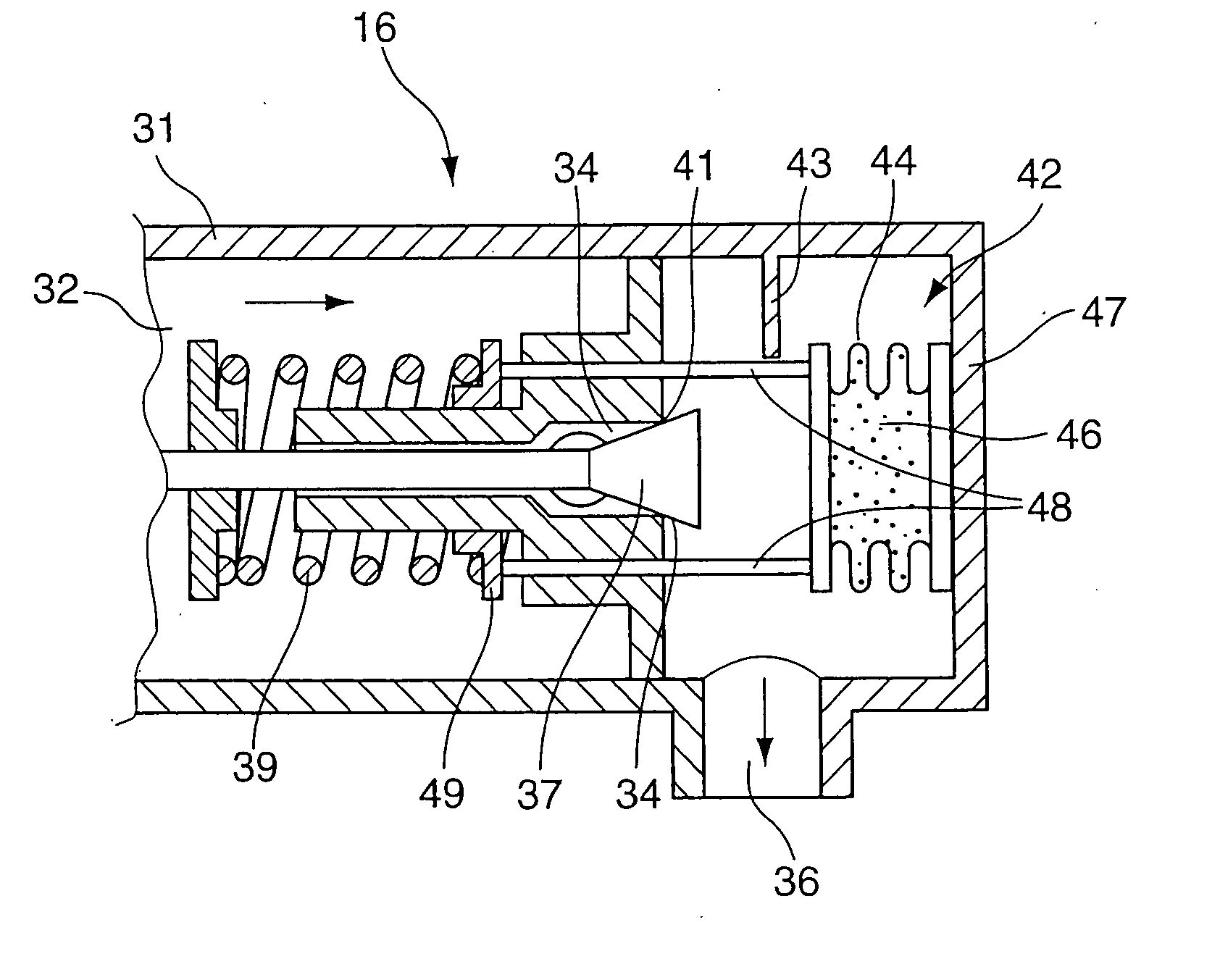
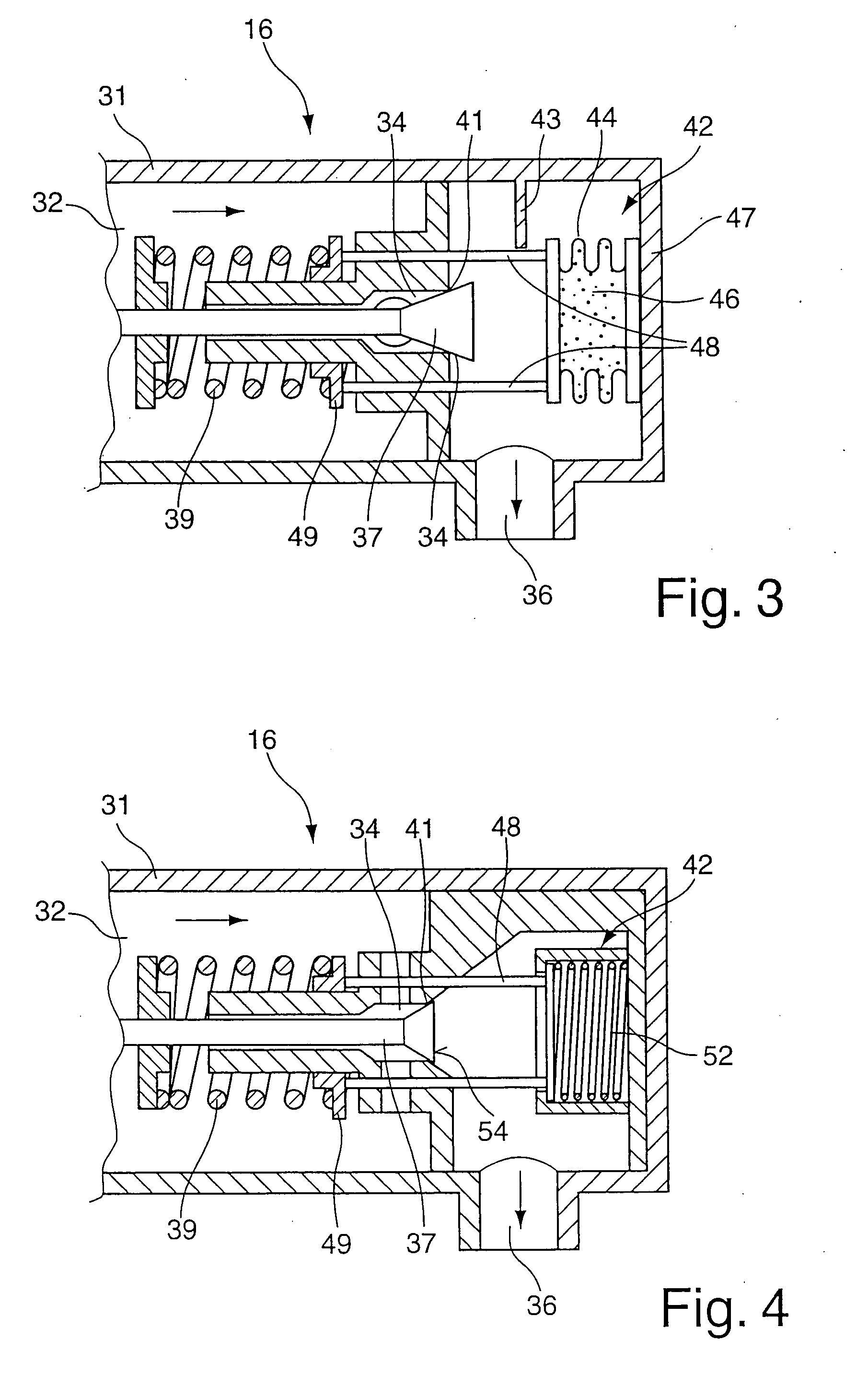
  • Application Information

AI Technical Summary

Benefits of technology

[0006] The invention is therefore based on the object of developing a method for controlling the expansion valve and an expansion valve of the type mentioned at the beginning to the effect that, after long inoperative periods and at high ambient temperatures, a rapid response characteristic is provided thus resulting in rapid cooling of the space to be cooled.
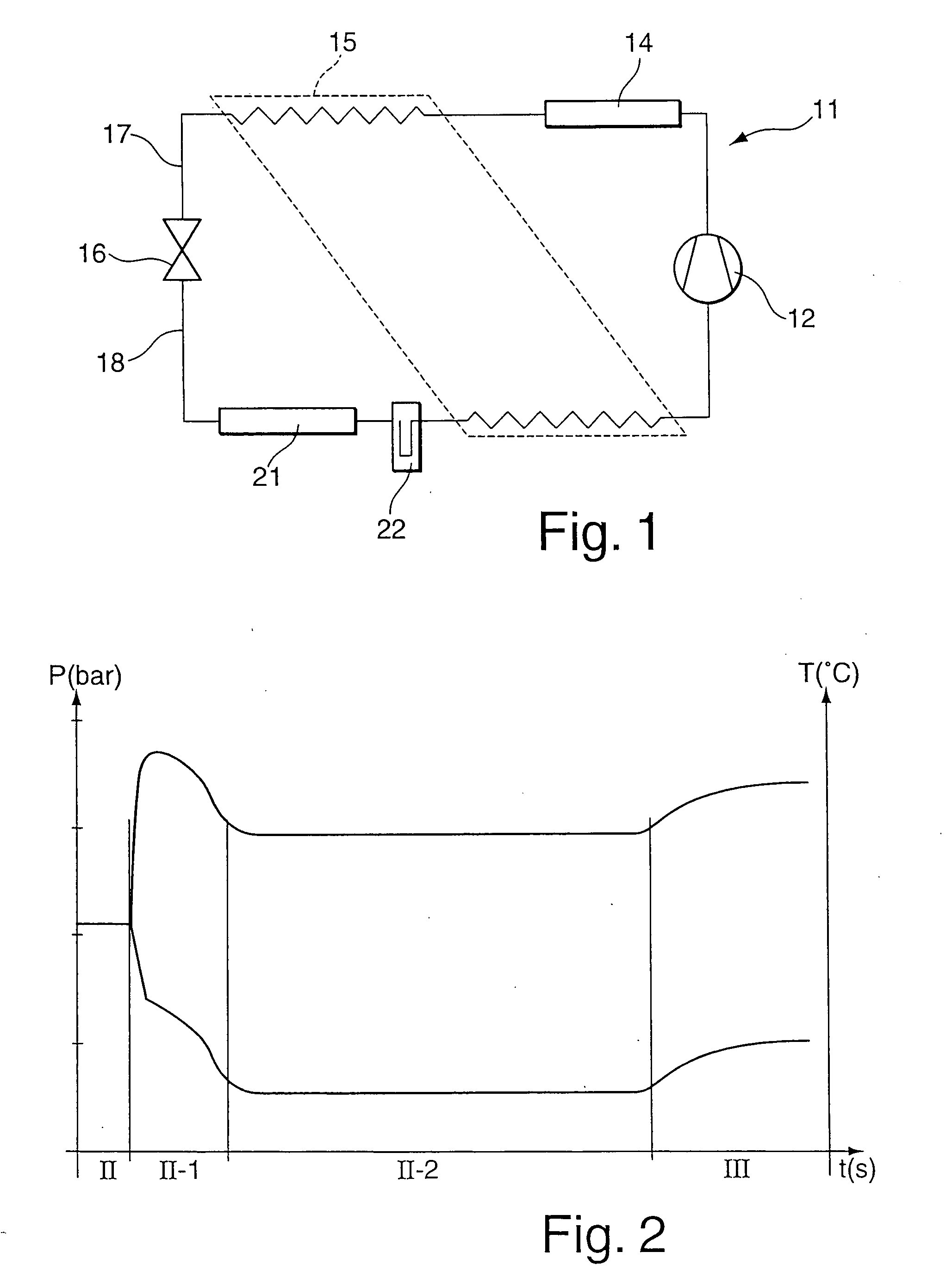
[0008] The effect obtained by the method according to the invention for controlling the expansion valve is that an opening characteristic of the valve-closing member of the expansion valve controlled by differential pressure is displaced to a lower opening pressure, as a result of which the response characteristic of the refrigerant circuit is increased. This is based on the effect that, by displacing the valve characteristic towards lower values, a premature opening of the valve-closing member takes place, thus resulting in an increase of the mass flow of refrigerant obtained between the very rapidly rising high pressure and the less steeply dropping low pressure. When the refrigerant circuit is switched on, the compressor is switched on and, on the high-pressure side, reaches, within a few seconds, the maximum permissible pressure which is approximately maintained over a starting period. By increasing the mass flow of refrigerant under such conditions, rapid dropping of the low pressure is achieved because of the cooling of the cooling-circuit components on the low-pressure side which has taken place.
[0009] The obtaining of a relatively large pressure differential directly after an inoperative air-conditioning system is started up is made possible, according to the invention, by an expansion valve, in particular for carrying out the method according to the features of claim 1, with an adjusting element which is on the low-pressure side and, via a predetermined threshold value, reduces, as a function of a rising temperature on the low-pressure side or a rising pressure, a closing force of the resetting device acting on the valve-closing member such that a refrigerant flow flows through the passage opening. For this purpose, according to a first embodiment, the adjusting, element is used to activate at least one actuating element which acts on the resetting device of the valve-closing member. This improves the response characteristic of the refrigerant circuit. Cooling is obtained even after a few seconds. As an alternative to reducing the closing force acting on the valve-closing member by the at least one actuating element, an embodiment is provided, in which a passage is provided parallel to the passage opening, which passage forms a bypass valve with and is closed by an adjusting element which can be activated on the low-pressure side. When a predetermined threshold value of the low pressure or of the temperature on the low-pressure side is exceeded, the bypass valve opens such that, at high pressures or temperatures on the low-pressure side, in particular when starting under high ambient temperatures, a relatively large refrigerant flow expands and cooling occurs at an even earlier time.
[0010] According to an advantageous refinement of the expansion valve, it is provided that the adjusting element; which can be activated by low pressure, is designed as an expansion bellows, in particular with an inert gas filling, and comprises tappets which act on a resetting device acting on the high-pressure side in order to reduce the closing force of the valve-closing member closing the passage opening. As the low pressure or evaporation pressure of the refrigerant in the expansion valve rises, for example because of a high ambient pressure or heating of the parts of the air-conditioning system, the free length of the expansion bellows is reduced in accordance with the pressure. Tappets arranged on the expansion bellows protrude from the low-pressure side to the high-pressure side and act on a setting valve for regulating the closing force. When the stroke length of the expansion bellows is reduced, the closing force, in particular the prestressing force of a resetting device designed as a spring element, is reduced such that the valve-closing member opens the passage opening at an earlier time and a mass flow of refrigerant flows through the expansion valve.
[0017] According to a further advantageous refinement of the pressure-dependent bypass valve, it is provided that the valve-closing member closing the passage is arranged on the high-pressure side and has a closing element, in particular spring element, acting towards the valve seat. As a result, a closed position can be ensured when the vehicle is inoperative.

Problems solved by technology

It generally takes too long for the maximum cooling power to be obtained under high ambient temperatures.

Method used


Image

  • Method for controlling an expansion valve and expansion valve, in particular for vehicle air-conditioning systems operated with CO2 as the refrigerant
  • Method for controlling an expansion valve and expansion valve, in particular for vehicle air-conditioning systems operated with CO2 as the refrigerant
  • Method for controlling an expansion valve and expansion valve, in particular for vehicle air-conditioning systems operated with CO2 as the refrigerant

Examples


Embodiment Construction

[0027]FIG. 1 illustrates a refrigerant circuit 11 which is preferably operated with CO2. This refrigerant circuit 11 is used, for example, as a vehicle air-conditioning system. A compressor 12 feeds the compressed refrigerant on the high-pressure side to an outside heat exchanger 14. The latter is connected to the surroundings and outputs heat outwards. Connected downstream of the latter is an inside heat exchanger 15 which feeds the refrigerant to an expansion valve 16 via a feed line 17. Upstream of the expansion valve 16 on the high-pressure side there is an input pressure which, for example in summer, can be 120 bar. The refrigerant flows through the expansion valve 16 and passes to the low-pressure side. On the output side, the expansion valve 16 has pressures of between 35 and 45 bar under stationary conditions. The refrigerant, which is cooled by the relaxation of the pressure, passes via a removal line 18 into the inside heat exchanger 21 and will remove heat from the surrou...


PUM


Abstract

The invention relates to a method for controlling an expansion valve, in particular for vehicle air-conditioning systems operated with CO2 as the refrigerant, with a valve housing which has a feed opening and a removal opening, with a valve-closing member which closes a valve seat of a passage opening arranged between the feed and removal openings, and with a resetting device which acts in the closing direction of the valve-closing member, an adjusting element, which is assigned to the valve-closing member, on the low-pressure side being activated via a predetermined threshold value as the low pressure rises or as the temperature on the low-pressure side rises and actuates at least one actuating element by means of which a closing force of the resetting device acting on the valve-closing member is reduced such that a passage opening is enlarged or a passage of a bypass valve arranged on the low-pressure side, which passage is arranged parallel to the passage opening, is opened.

Description

[0001] Applicant herein incorporates by reference the following foreign priority document: German Appln. No. 10 2006 021 327.0, filed May 5, 2006. BACKGROUND OF THE INVENTION [0002] The invention relates to a method for controlling an expansion valve and to an expansion valve, in particular for vehicle air-conditioning systems operated with CO2 as the refrigerant, in accordance with the precharacterizing clause of Claim 1 and 2. [0003] DE 10 2004 010 997 B3 discloses an expansion valve and a method for controlling it, in which the opening and closing movement of a valve-closing member is set as a function of the pressure differential present in a feed opening on the high-pressure side and in a removal opening of the expansion valve on the low-pressure side. A resetting device keeps the valve-closing member in a closed position when the refrigerant circuit is not in operation. [0004] An expansion valve of this type which operates as a function of the pressure differential between the...

Claims


Application Information

Patent Timeline
Patent Type & Authority Applications(United States)
IPC IPC(8): F25B41/04
CPCF25B9/008F25B41/062F25B2500/07F25B2341/063F25B2400/0411F25B2309/061F25B41/325F25B41/33F25B41/36
Inventor ROBIN, JEAN-JACQUES
Owner OTTO EGELHOF
Learn More