Light converging-type solar photovoltaic apparatus

Inactive Publication Date: 2007-12-27
DAIDO STEEL CO LTD
View PDF13 Cites 31 Cited by
  • Summary
  • Abstract
  • Description
  • Claims
  • Application Information

AI Technical Summary

Benefits of technology

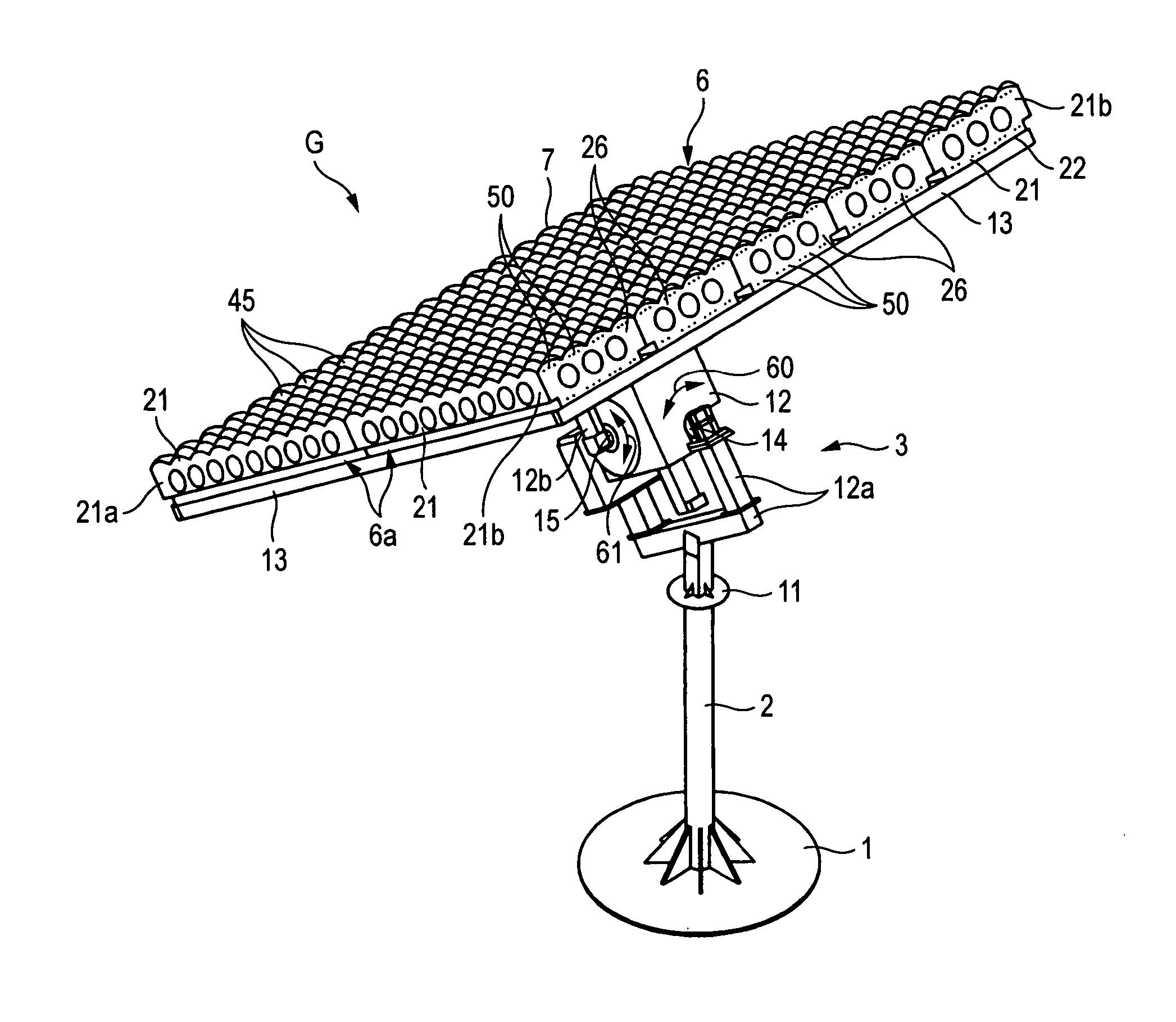
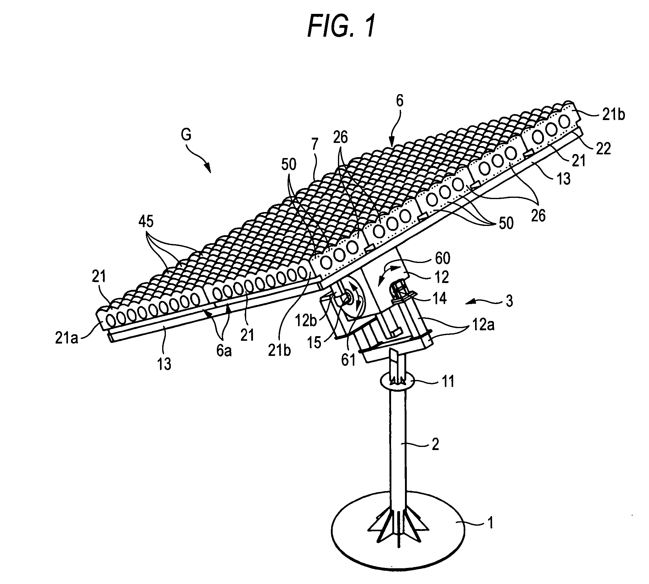
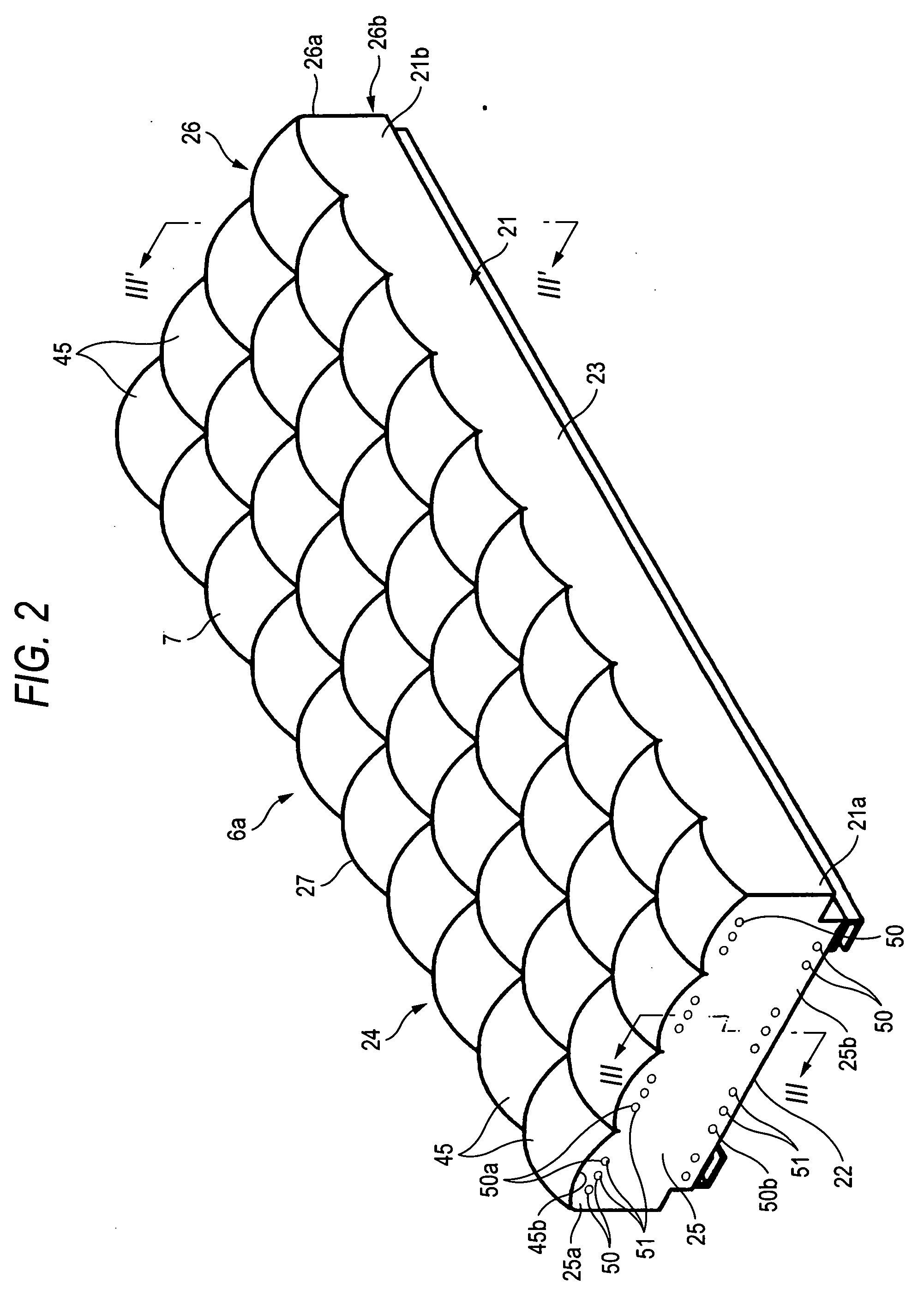
[0019] As described above, according to the invention, the Fresnel lenses converge the sunlight and irradiate on the solar battery cells to generate electric power. Further, even when dew drops appear in the grooves of the Fresnel lenses, the air flows from the lower end side of the case being inclined toward the upper end side thereof due to the opening portions provided at each of the opposing surfaces of the peripheral members of the case, so that the water collected in the grooves of the Fresnel lenses can be removed smoothly. Thus, the degraded time period of the light converging abil

Problems solved by technology

Thus, there arises a problem that dust or insects enter into a case via the through holes to pollute the Fresnel lenses and the solar battery cells thereby to degrade the electric power generation efficiency.
Due to the dew drops, there arises a problem that water collected within the grooves degrades the light converging ability of the lenses to remarkably degrade the electric-p

Method used


Image

  • Light converging-type solar photovoltaic apparatus
  • Light converging-type solar photovoltaic apparatus
  • Light converging-type solar photovoltaic apparatus

Examples


Example

Embodiment 1

[0119]FIG. 6 shows a concrete example of the disposing positions, the number and the size of the opening portions 50. Numerals with parentheses shown in FIG. 6 represent the sizes (mm). For example, the size of the opening portion is 12 mm in its diameter.

Example

Embodiment 2

[0120] An example of the experimentation will be shown as to the relation between the entire area of the opening portions provided at the case of the light converging-type power generation module 6a and the condition of forming a dew drop.

(1) Method:

[0121] Twelve holes (opening portions) of f12 are provided at each of the upper and lower portions of each of the opposing peripheral members in the longitudinal direction of the power generation module (that is, a mini module (formed by 6 lenses each having a square size of 14 cm×14 cm)) with a capacity of 18,200 cm3, that is, 12×2×2=48 opening portions in total are provided. Each of the holes is covered by a stainless mesh with a rate of opening area of 42%. These holes are selectively covered by a paper tape to change the entire area of the opening portions, whereby the presence / non-presence of a dew drop is checked.

(2) Discrimination Condition of Dew Drop:

[0122] Water was soaked into a gauze of 5 cm square on the p...

Example

Embodiment 3

[0126] Next the explanation will be made with reference to FIG. 7 as to the generator which differs in the shape of the opening portions from that of FIGS. 1 to 6.

[0127] In FIG. 7, portions considered to be identical or similar in the functions, properties or features etc. to those of FIGS. 1 to 6 are referred to by the symbols common to those of FIGS. 1 to 6, with explanation thereof being omitted. (Further, in FIGS. 3B, 3C) used in the following explanation, portions considered to be identical in the similar manner are referred to by the symbols common to those of FIGS. 1 to 6, with explanation thereof being omitted.)

[0128]58 depicts opening portions each formed in an elongated shape. Like the opening portions 50 shown in FIGS. 1 to 6, the setting positions of the opening portions 58 in the case and the arrangement of the opening portions 58 in the peripheral members are set in a manner that air ventilation paths are formed in the space 28 within the case.

[0129] Al...


PUM


Abstract

The present invention provides a light converging-type solar photovoltaic apparatus having: a case having: a bottom member; a peripheral member; and an upper member so as to form a space in the case, the case inclining so as to face the upper member to the sun; a plurality of Fresnel lenses provided at the upper member, the Fresnel lenses converging sun light; a plurality of solar battery cells provided in the case, the solar battery cells each receiving each sun light converged by the Fresnel lenses to generate electric power, the peripheral member having surfaces opposed to each other, the opposed surfaces each having at least one opening portion, and a vent valve provided at each opening portion, the vent valve having a mesh interrupting ventilation upon a water film being formed on the mesh.

Description

FIELD OF THE INVENTION [0001] The present invention relates to a light converging-type solar photovoltaic apparatus in which sunlight is converged on a solar battery cell via a Fresnel lens to generate electric power. BACKGROUND OF THE INVENTION [0002] A light converging-type solar photovoltaic apparatus of a related art includes a light converging plate on which a plurality of Fresnel lenses each for converging sunlight are juxtaposed and a supporting plate disposed in parallel to the light converging plate with a predetermined distance therebetween. A plurality of solar battery cells, which receive the sunlight converged by the plurality of Fresnel lenses, respectively, are provided on the supporting plate. [0003] The sunlight is converged by the Fresnel lenses and irradiated on the solar battery cells, respectively, whereby sunlight energy is converted into electric power to generate electric power (see a reference 1, for example). [0004] [Reference 1] JP-A-2005-142373 [0005] The...

Claims


Application Information

Patent Timeline
IPC IPC(8): H01L31/048
CPCF24J2/085F24J2/523F24J2/542H01L31/048H01L31/0547Y02E10/47Y02E10/52F24J2/4618H01L31/0543Y02E10/43F24S25/10F24S30/452F24S23/31F24S40/53H01L31/054H01L31/024
Inventor UOZUMI, HISAFUMIARAKI, KENJIYANO, TAIZO
Owner DAIDO STEEL CO LTD
Why Eureka
Try Eureka