
Tire Labeling System

a labeling system and tire technology, applied in the field of tire labeling system, can solve the problems of difficult to completely remove the label before applying a new one, cost of replacing labels and scrapping old labels, and the effect of increasing the cost of scrapping

Active Publication Date: 2007-12-27
COMML TIME SHARING
View PDF8 Cites 12 Cited by
  • Summary
  • Abstract
  • Description
  • Claims
  • Application Information

AI Technical Summary

Benefits of technology

[0009] In accordance with another aspect of the present invention, a tire labeling system includes an applicator, and a frame carrying the applicator, the applicator including a head and an arm supporting the head, the arm being rotatably mounted relative to the frame, and rotatable between a pick-up position and at least one application position, and the frame facilitating movement of the application along a first axis, a second axis, and a third axis.
[0010] In accordance with still another aspect of the present invention, a tire labeling system for printing labels, removing labels from a backing, and positioning labels on the surfaces of tires including a printer for printing labels, a platform receiving the labels, a take-up spool for gathering the backing, an applicator, and a frame carrying the applicator, the frame facilitating movement of the applicator along a first axis, a second axis, and a third axis.

Problems solved by technology

The old label must be removed, and, due to the strong adhesive used to make sure the label does not come off during shipment, it is often difficult to completely remove the label before applying a new one.
When viewed in the context of the extremely large number of tires produced and sold, the cost of replacing labels and scrapping old labels becomes significant, and may be on the order of millions of dollars.

Method used


Image

  • Tire Labeling System
  • Tire Labeling System
  • Tire Labeling System

Examples


Embodiment Construction

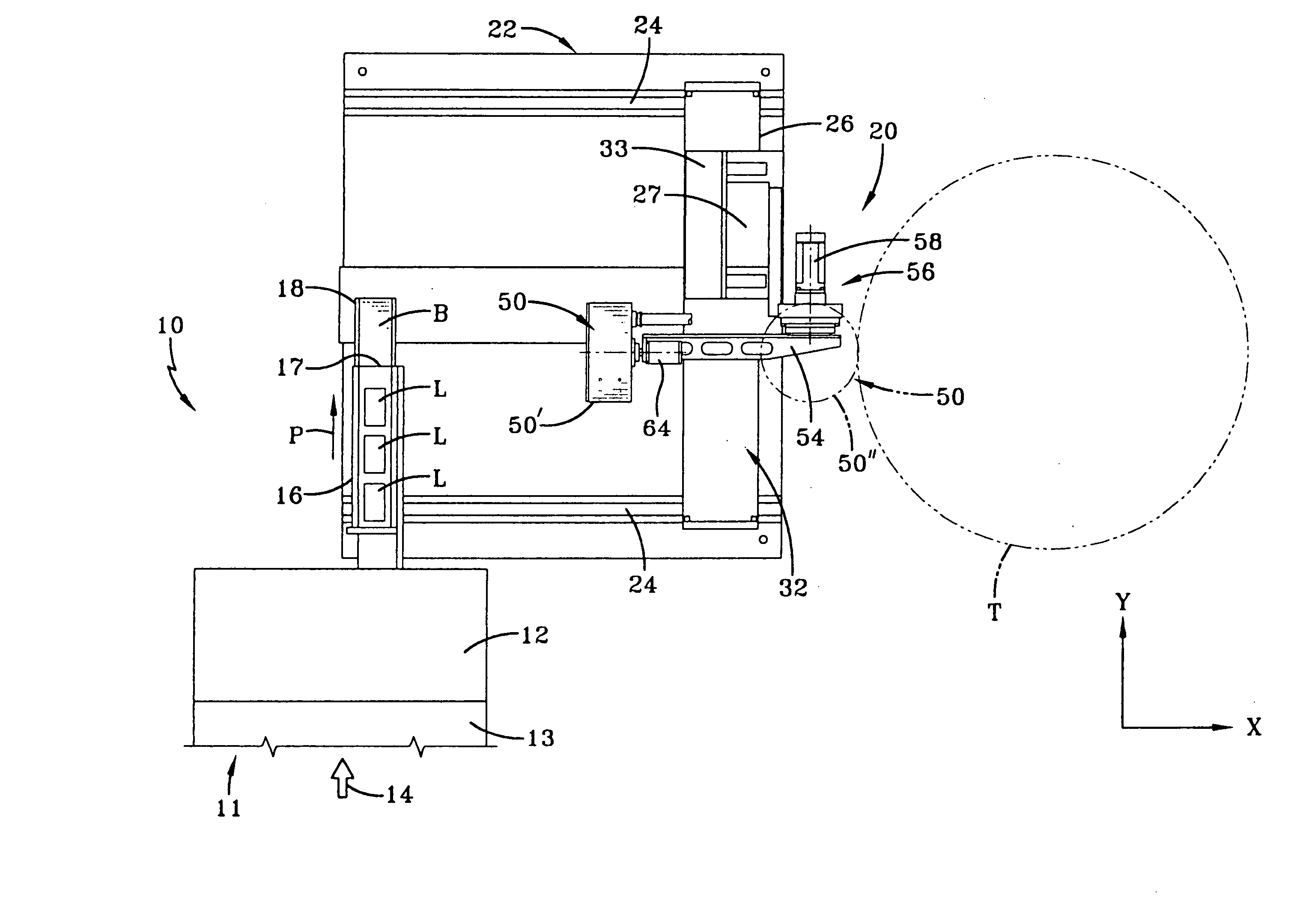
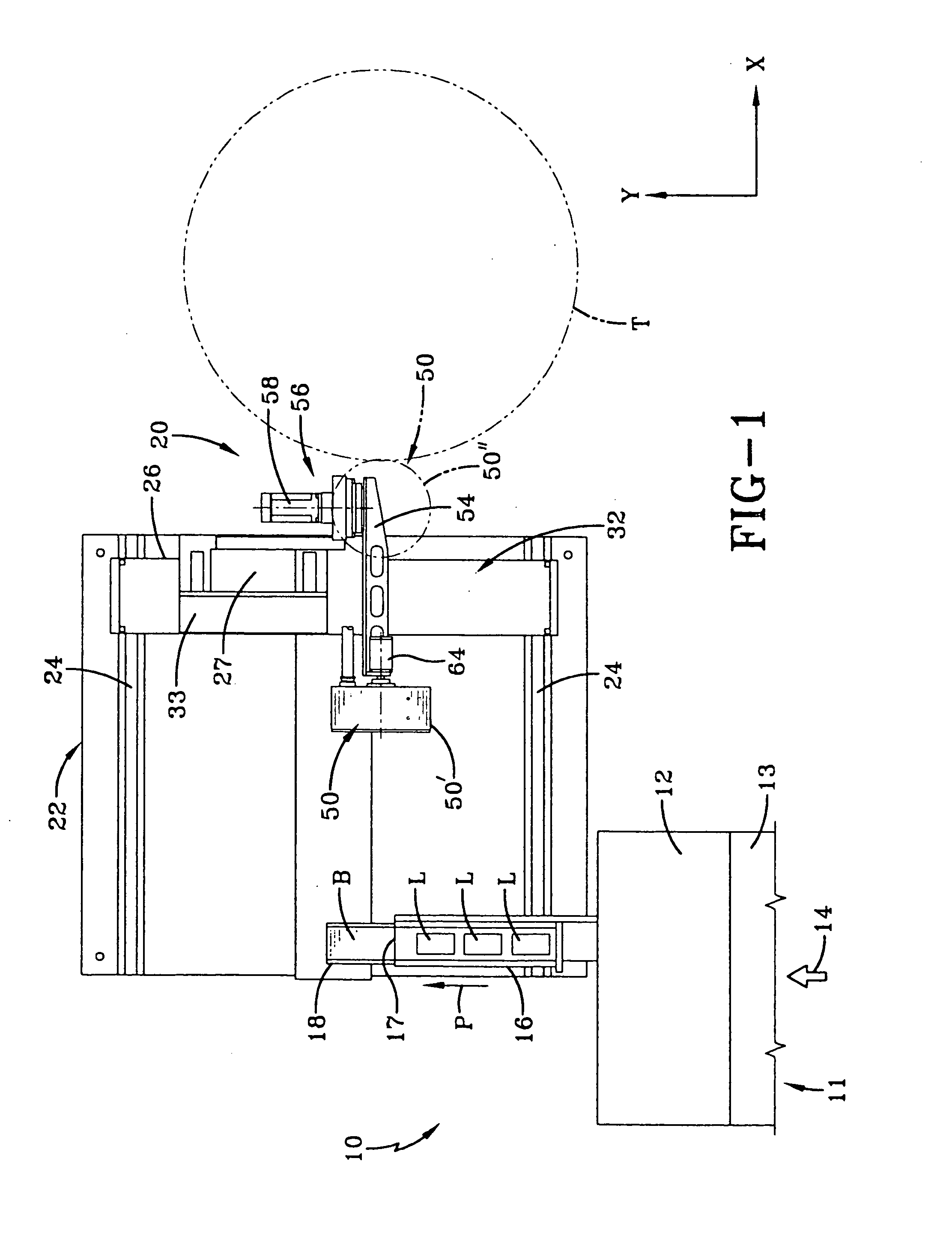
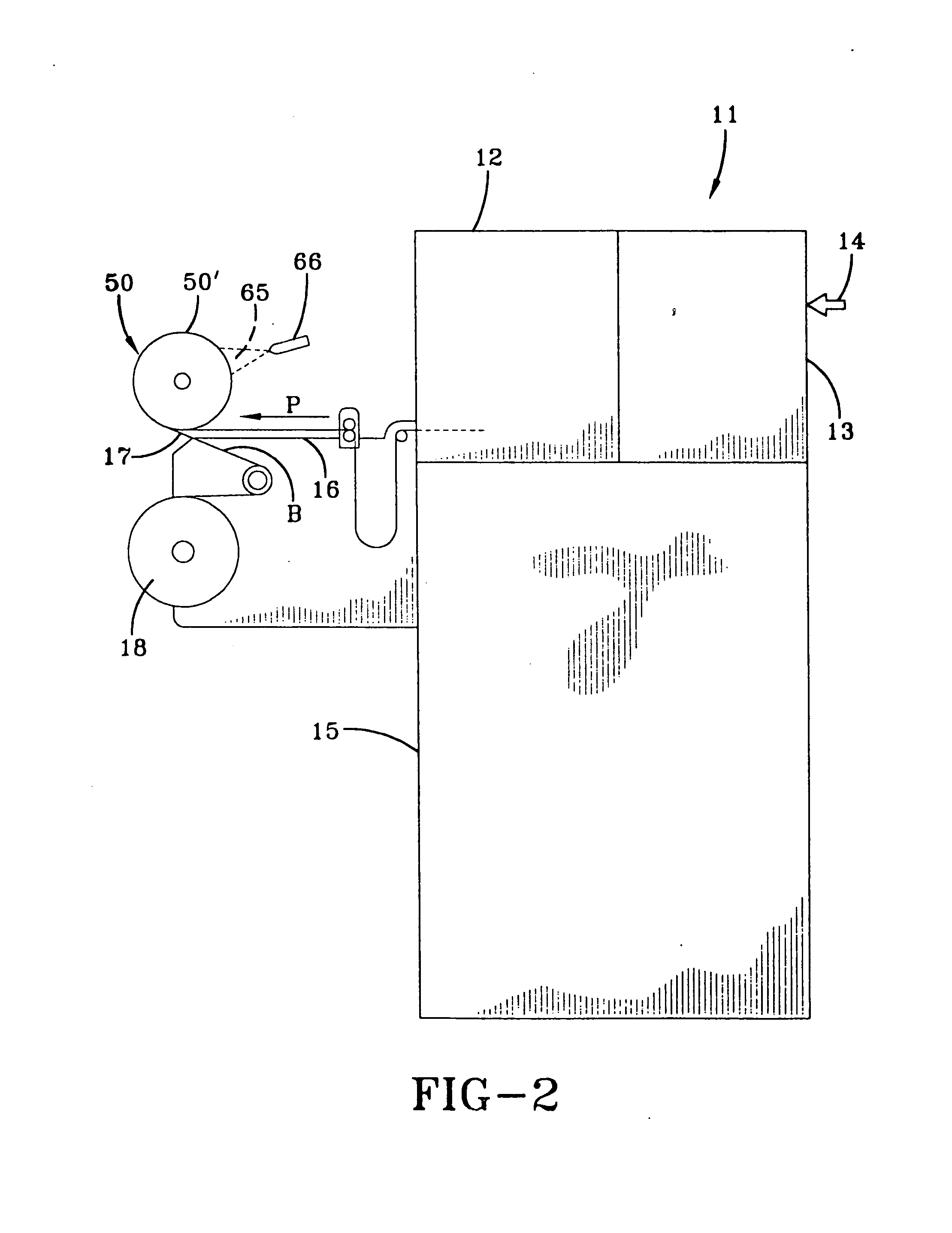
[0019] A tire labeling system according to the concepts of the present invention is generally indicated by the numeral 10 in FIGS. 1 and 3. The tire label system 10 may include a printer assembly, generally indicated by the numeral 11 that includes a printer 12 connected to a computer, generally indicated by the numeral 13, that provides tire information 14 to the printer 12.

[0020] As shown in FIGS. 1, 3 and 4, the computer 13 may be any device suitable for storing the tire information 14 for tires T, and, thereafter, providing that information to the printer 12. The tire information 14 may be loaded on the computer 13 by any known method including portable memory storage devices, such as floppy disks, compact disks, flash memory drives, portable hard drives, and the like, by a network connection with an appropriate database, or based on input from any manual or automated scanning device that reads the tire information 14 from the tires T. It will be appreciated that the printer 12...


PUM

PropertyMeasurementUnit
movementaaaaaaaaaa
self-adhesiveaaaaaaaaaa
vacuumaaaaaaaaaa

Abstract

A tire labeling system (10) for printing a label (L) and applying the label (L) on a surface of a tire (T). A printer (12) is provided to print the label and an applicator (20) is provided to transfer the label (L) from the printer (12) to the tire (T) and apply the label (L) to the tire (T).

Description

RELATED PATENT APPLICATIONS [0001] This is a §371 application of PCT / US2005 / 006546 filed Feb. 28, 2005, which claims the benefit of U.S. Provisional Application No. 60 / 548,549 filed on Feb. 27, 2004; wherein both applications are expressly incorporated herein by reference.TECHNICAL FIELD [0002] In general, the present invention relates to a tire labeling system. More particularly, the present invention relates to a tire labeling system that picks up a label from a printer moves to a selected position, and applies the label to a tire. BACKGROUND OF THE INVENTION [0003] Tire labels are applied to all new tires and contain information about the tire's characteristics and other information required by law. To save costs, large quantities of labels are printed on rolls that are shipped to manufacturing facilities to be applied to the tires. The preprinted labels are loaded into a labeling machine located adjacent to a conveyor. As tires travel on the conveyor, they are brought into conta...

Claims


Application Information

Patent Timeline
Patent Type & Authority Applications(United States)
IPC IPC(8): B60C19/00B65C3/00B65C3/26B65C5/00B65C5/02B65C9/18B65C9/46
CPCB65C9/46B65C9/1884
Inventor SYMENS, RONALDDELMORO, RICHARD
Owner COMML TIME SHARING
Learn More