Dual-chamber fluid pump for a multi-fluid electronics cooling system and method

Active Publication Date: 2007-12-27
LENOVO GLOBAL TECH INT LTD
View PDF12 Cites 33 Cited by
  • Summary
  • Abstract
  • Description
  • Claims
  • Application Information

AI Technical Summary

Benefits of technology

[0005]The need to cool current and future high heat load, high heat flux electronic devices requires development of aggressive thermal management techniques, such as liquid impingement approaches to cool the electronic devices

Problems solved by technology

This heat must be removed from the devices in order to maintain device junction temperatures within desirable limits, with failure to remove the heat thus produced resulting in increased device temperatures, potentially leading to thermal runaway conditions.
First, power dissipation, and therefore heat production, increases as device operating frequencies increase.
Further, as more and more devices are packed onto a single chip, power density (Watts / cm2) increases, resulting in the need to remove more power from a given size chip or module.
These trends have combined to create applications where it is no longer desirable to remove heat from modern devices solely by traditional air cooling methods, such as by using air cooled heat sinks with heat pipes or vapor chambers.
Air cooling techniques are inherently limited in their ability to extract heat from an electronic device with high power density.

Method used


Image

  • Dual-chamber fluid pump for a multi-fluid electronics cooling system and method
  • Dual-chamber fluid pump for a multi-fluid electronics cooling system and method
  • Dual-chamber fluid pump for a multi-fluid electronics cooling system and method

Examples


Embodiment Construction

[0024]As used herein “electronic device” comprises any heat generating electronic component of a computer system or other electronic system requiring cooling. In one example, the electronic device is or includes one or more integrated circuit chips, and / or electronic components. The term “fluid cooled electronic module” includes any electronic module with liquid cooling and at least one electronic device, with single-chip modules and multi-chip modules being examples of a cooled electronic module as described herein. The “surface to be cooled” refers to a surface of one or more electronic devices, or to an exposed surface of a thermal cap, thermal spreader, passivation layer, or other surface in contact with the one or more electronic devices, and through which heat generated by the electronic device(s) is to be extracted.

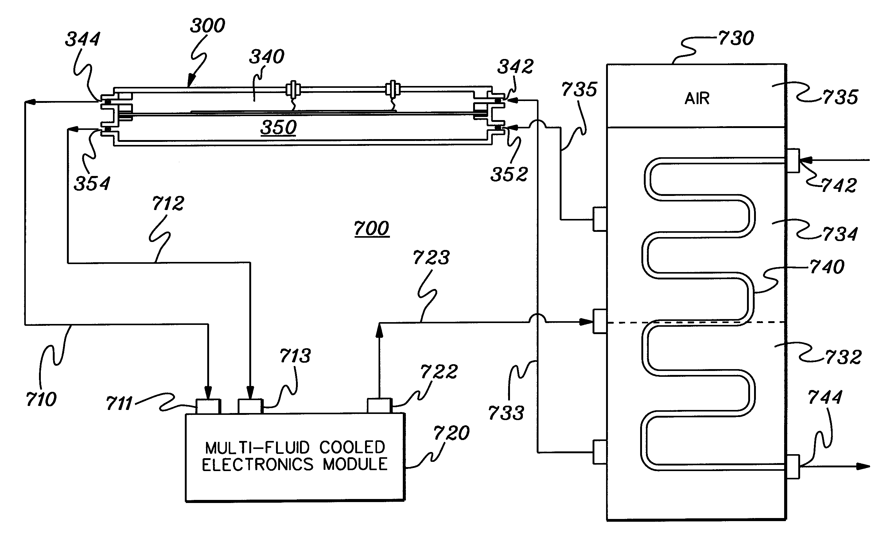
[0025]Generally stated, provided herein is an enhanced dual-chamber fluid pump and cooled electronics system and method employing the enhanced pump. In one embodim...


PUM


Abstract

A dual-chamber fluid pump is provided for a multi-fluid electronics cooling system and method. The pump has a first fluid path for pumping a first fluid coolant and a second fluid path for pumping a second fluid coolant, with the first fluid path including a first pumping chamber and the second fluid path including a second pumping chamber. The first and second pumping chambers are separated by at least one diaphragm, and an actuator is coupled to the diaphragm for transitioning the diaphragm between a first position and a second position. Transitioning of the diaphragm to the first position pumps first fluid coolant from the first pumping chamber while concurrently drawing second fluid coolant into the second pumping chamber, and transitioning of the diaphragm to the second position pumps second fluid coolant from the second pumping chamber while concurrently drawing first fluid coolant into the first pumping chamber.

Description

CROSS-REFERENCE TO RELATED APPLICATION [0001]This application contains subject matter which is related to the subject matter of the following co-filed application, which is assigned to the same assignee as this application and which is hereby incorporated herein by reference in its entirety:[0002]“Multi-Fluid Cooling System, Cooled Electronics Module, and Methods of Fabrication Thereof”, Campbell et al., Ser. No. ______, co-filed herewith (Attorney Docket No.: POU920060104US1).TECHNICAL FIELD [0003]The present invention relates generally to heat transfer mechanisms, and more particularly, to cooling systems, cooled electronics modules and methods of fabrication thereof for removing heat generated by one or more electronic devices. Still more particularly, the present invention relates to multi-fluid cooling systems and methods of cooling one or more electronic devices, and in particular, to a multi-chamber fluid pump for pumping different fluids through a multi-fluid cooling system....

Claims


Application Information

Patent Timeline
IPC IPC(8): H05K7/20
CPCH05K7/20218
Inventor CAMPBELL, LEVI A.CHU, RICHARD C.ELLSWORTH, MICHAEL J.IYENGAR, MADHUSUDAN K.SCHMIDT, ROGER R.SIMONS, ROBERT E.
Owner LENOVO GLOBAL TECH INT LTD
Why Eureka
Try Eureka