Shock-release fluid fracturing method and apparatus

a fluid fracturing and shock-release technology, applied in fluid removal, earth-moving drilling and mining, borehole/well accessories, etc., can solve the problem of less effective fracture of formations using such known processes

Inactive Publication Date: 2007-12-27
CALFRAC WELL SERVICES
View PDF7 Cites 28 Cited by
  • Summary
  • Abstract
  • Description
  • Claims
  • Application Information

AI Technical Summary

Problems solved by technology

It is believed that some formations are less effectively fractured using such known processes.

Method used


Image

  • Shock-release fluid fracturing method and apparatus
  • Shock-release fluid fracturing method and apparatus
  • Shock-release fluid fracturing method and apparatus

Examples


Embodiment Construction

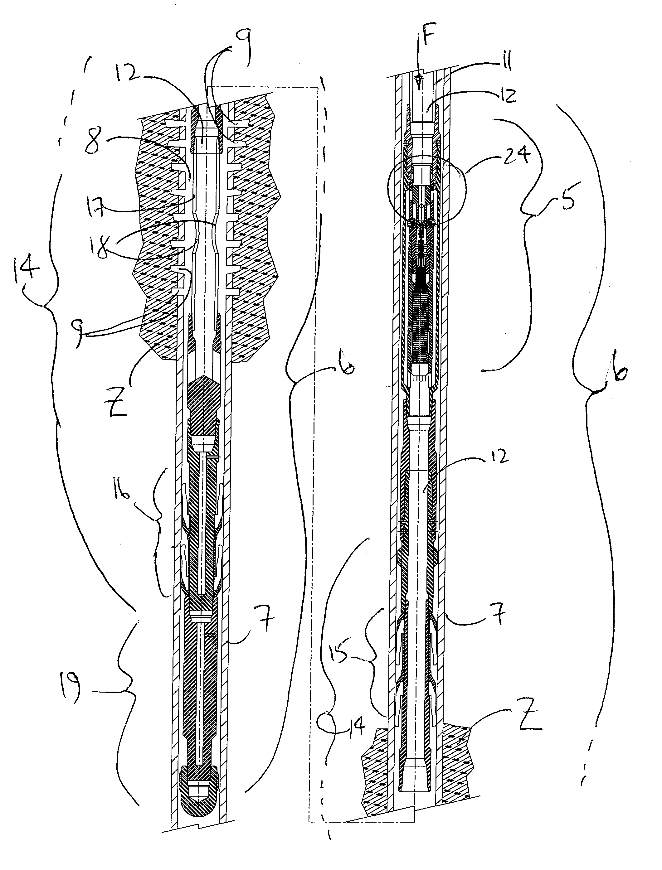
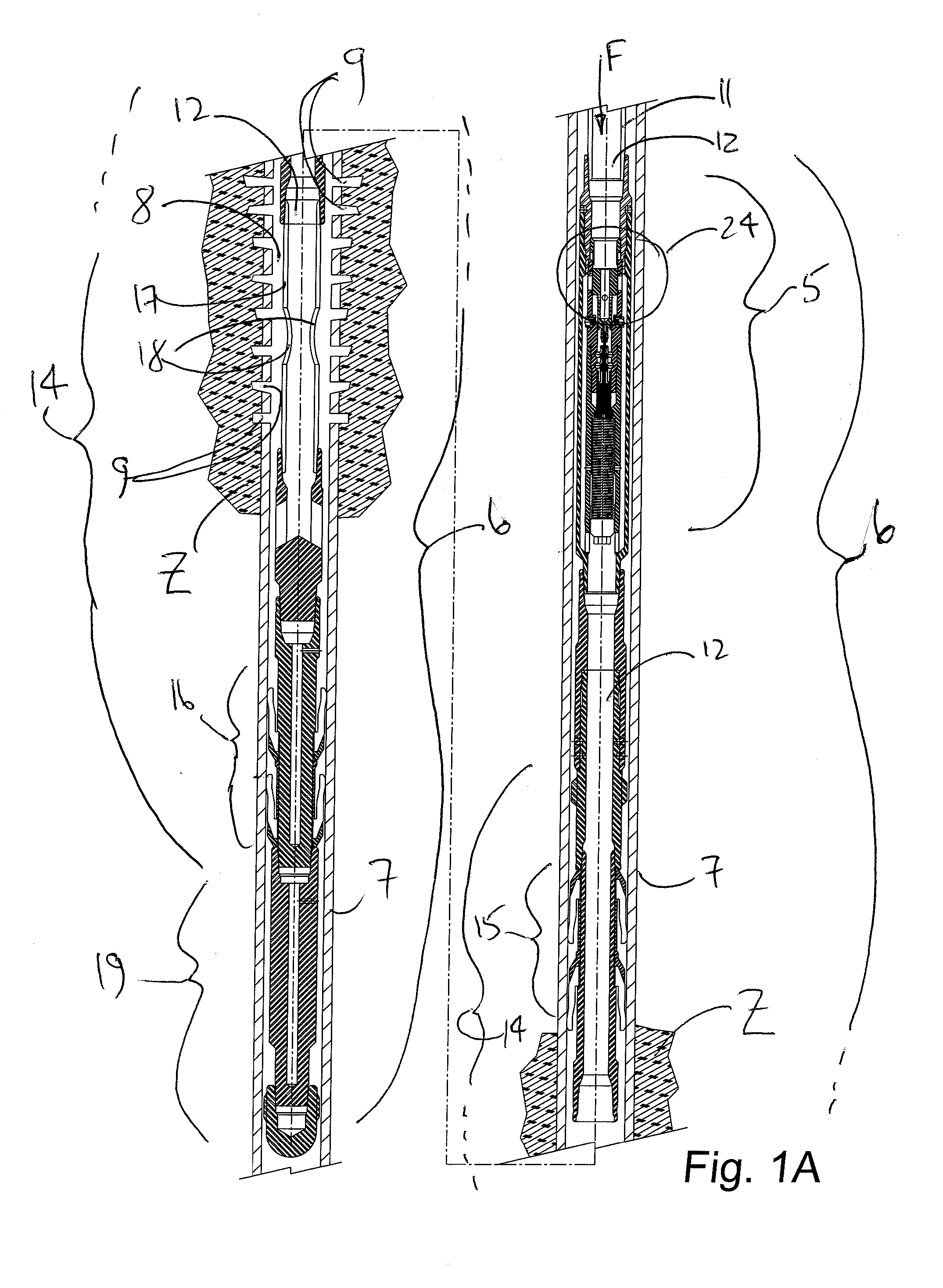
[0020]With reference to FIG. 1A, a shock tool 5 is provided for fracturing subterranean formations Z penetrated by a wellbore (context not shown). In an embodiment of the invention, the shock tool 5 is part of a tool assembly 6 conveyed downhole for actuation in the wellbore, preferably a wellbore having casing 7.

[0021]The tool assembly is lowered downhole into the casing 7 on a conveyance string 11 such as on wireline, jointed tubulars or coiled tubing. The shock tool is positioned in the vicinity of the formation Z.

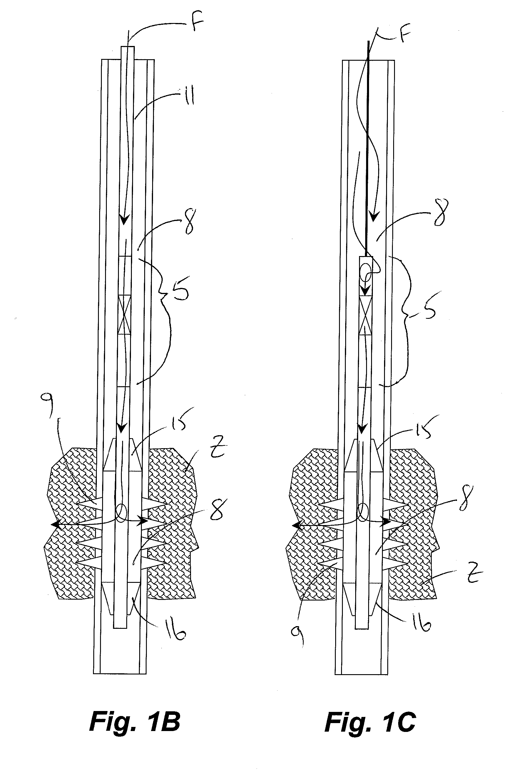
[0022]As is conventional in fracturing formations, a zone is isolated in the formation Z and an annulus 8 is formed between the tool assembly 6 and the wellbore. The annulus 8 is in communication with the isolated zone in the formation, such as through perforations 9 in the casing 7. Fracturing fluid F is accumulated for sudden release through the shock tool 5.

[0023]In one embodiment as shown in FIGS. 1A and 1B, the conveyance string 11 has a bore 12 which is contiguous...


PUM


Abstract

A shock tool is adapted to a bottom hole tool assembly for isolating a zone in a subterranean formation accessed by a wellbore. Fracturing fluid such as nitrogen is accumulated at fracturing pressures uphole of the shock tool for subsequent and rapid release to the formation. Coal bed methane seams are particularly well suited to such a shock fracturing methodology. The tool assembly can be suspended from a conveyance string in which fluid is accumulated for shock release through a valve of the shock tool and through an injection tool to the zone isolated by the injection tool. After a first zone is shocked, the tool assembly can be moved to a new zone, or multiple shocks can be applied cyclically at the selected zone.

Description

FIELD OF THE INVENTION[0001]The invention relates to method and apparatus for improving the extent of fracturing of formations using a shock release of fracturing fluid.BACKGROUND OF THE INVENTION[0002]Conventional fluid fracturing of subterranean formations comprises positioning a tool in a cased wellbore traversing a zone to be fractured. The tool straddles perforations in the cased wellbore. Fluid is pumped down a tubular conduit from surface to the subterranean tool at a flow rate and pressure sufficient to hydraulically fracture the formation.[0003]The exact nature of the resulting fractures is not fully known and will vary for different formations. As set forth in U.S. Pat. No. 4,995,463 to Kramm et al., issued in 1991, the fracture mechanics and fluid flow behaviour in cleated, coal bed formations is substantially different that those in sandstone and the like which are more conventionally known for oil and gas operations.SUMMARY OF THE INVENTION[0004]A known method for hydra...

Claims


Application Information

Patent Timeline
Patent Type & Authority Applications(United States)
IPC IPC(8): E21B43/26
CPCE21B43/26E21B43/006
Inventor COLLINS, JAMESANDREYCHUK, MARK T.
Owner CALFRAC WELL SERVICES
Why Eureka
Try Eureka