Multifunction pouring spout with pivoting handle

a multi-functional, handle technology, applied in the direction of pliable tubular containers, containers preventing decay, sealing, etc., can solve the problems of aggravated paint running down the side of the can, virtually impossible to pour paint out of the can into a paint tray or other container, undesirable paint smears on walls, floors, etc., to prevent the dripping of paint

Inactive Publication Date: 2007-12-27
ALLWAY TOOLS
View PDF24 Cites 35 Cited by
  • Summary
  • Abstract
  • Description
  • Claims
  • Application Information

AI Technical Summary

Benefits of technology

[0008] Accordingly, it is an object of the present invention to provide a detachable pouring spout for a paint can, which optionally includes a removable lid, that prevents the entry of paint into the sealing groove at the opening of the can and prevents the dripping of paint along the exterior surface of the paint can.

Problems solved by technology

Most notably, the construction of a typical one-gallon size paint can makes it virtually impossible to pour paint out of the can into a paint tray or other container without paint trickling down the sides of the can after the paint is poured.
Excess paint dripping down the exterior of the can may cause undesirable paint smears on walls, floors, furniture and other items when the dripping paint accidentally comes in contact with one or more of these surfaces or objects.
Further, the problem of paint running down the side of the can is aggravated when a user rests a wet paintbrush horizontally across the top of the paint can, as many painters typically do during a break.
Paint from a wet paintbrush drips down the side of the can, causing similar problems noted above.
Further, there are a number of other common occurrences that often irritate painters and present additional difficulties.
The paint in this sealing groove poses the following problems: first, if the metal paint can lid is placed onto the can top and into the groove before the paint in it dries, the paint acts as an adhesive, sealing the lid to the can and making it more difficult to remove later on.
In addition, when the cover is subsequently re-installed, paint in the sealing groove spatters as the lid is tapped down, causing paint to be dispersed randomly on the painter or on a surface.
Similarly, these problems are also encountered when dipping a paintbrush in a paint can and then wiping the brush against the inner rim of the can to remove excess paint from the brush.
Although painters are aware of this problem, they choose to wipe the brush against the inner rim since the alternative (i.e., spreading the excess paint over a given area) may ruin the job at hand, thereby entirely undermining their efforts.
Moreover, although it is good practice to replace the paint lid on the can during a lunch break to keep the paint fresh, many fail to do so and introduce paint to the side of the can lid and in its sealing groove.
Another problem is that it is physically demanding to hold a paint can filled with paint by the wire handle that is provided on standard one-gallon paint cans due to the weight of the paint can when filled with paint.
Moreover, since the handle is positioned directly above the opening of the suspended paint can when holding the can by the handle, it interferes with the dipping of the paint brush into the can thereby forcing a user to locate and orient the brush so that it does not come into contact with the paint can handle.
Furthermore, in the context of smaller, one-quart paint containers where a handle is typically not provided therewith, it is particularly strenuous to continuously hold the can in a hand by outer side of the can without enduring muscle cramps and fatigue.

Method used


Image

  • Multifunction pouring spout with pivoting handle
  • Multifunction pouring spout with pivoting handle
  • Multifunction pouring spout with pivoting handle

Examples


Embodiment Construction

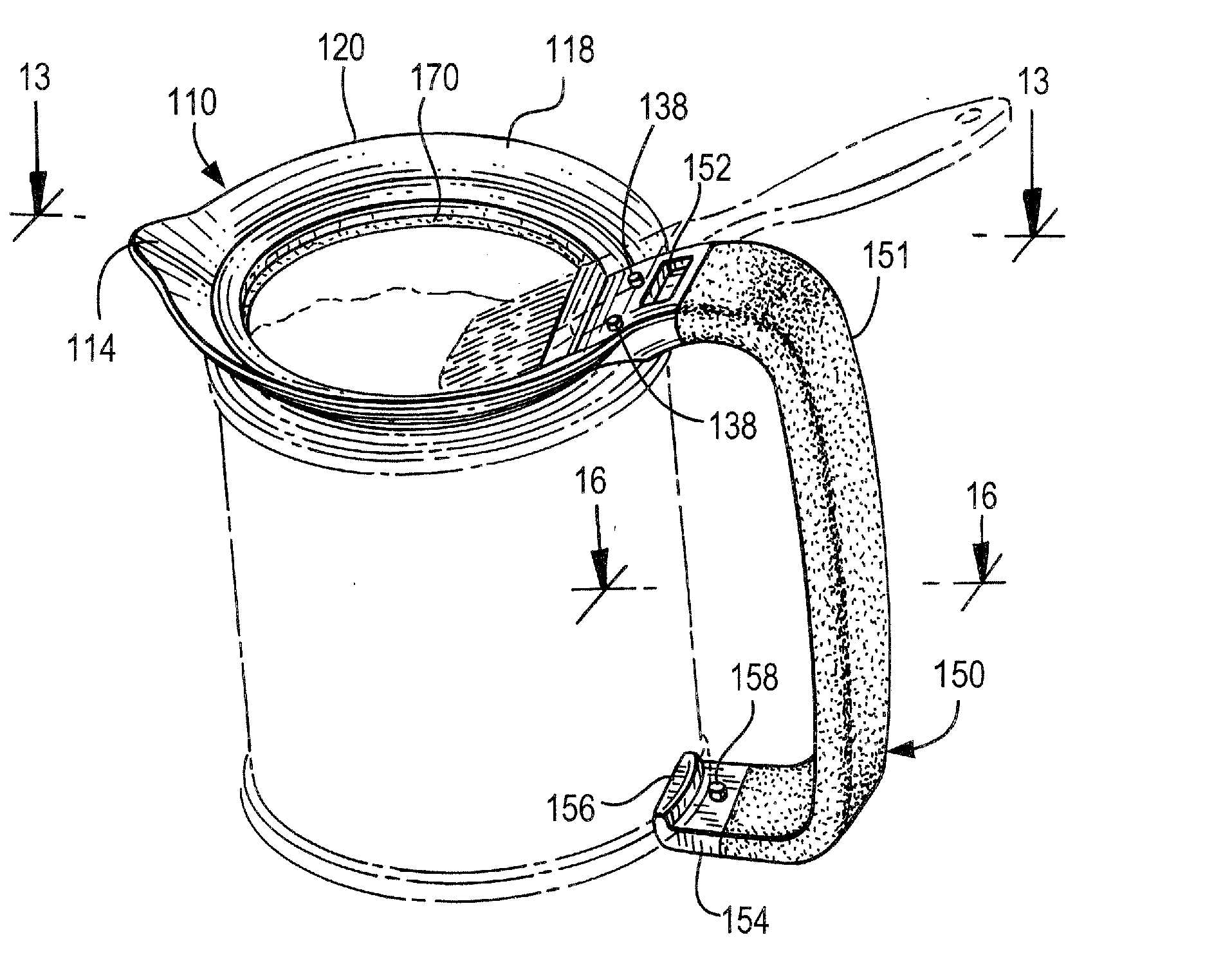
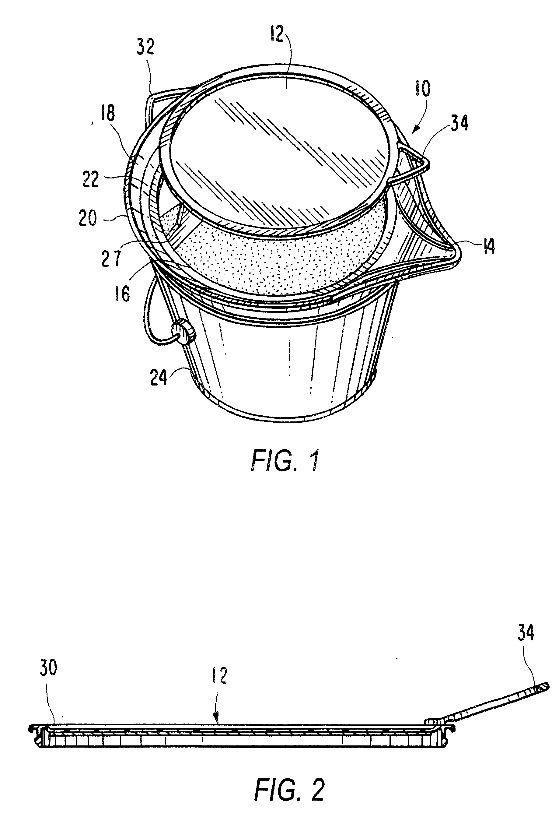
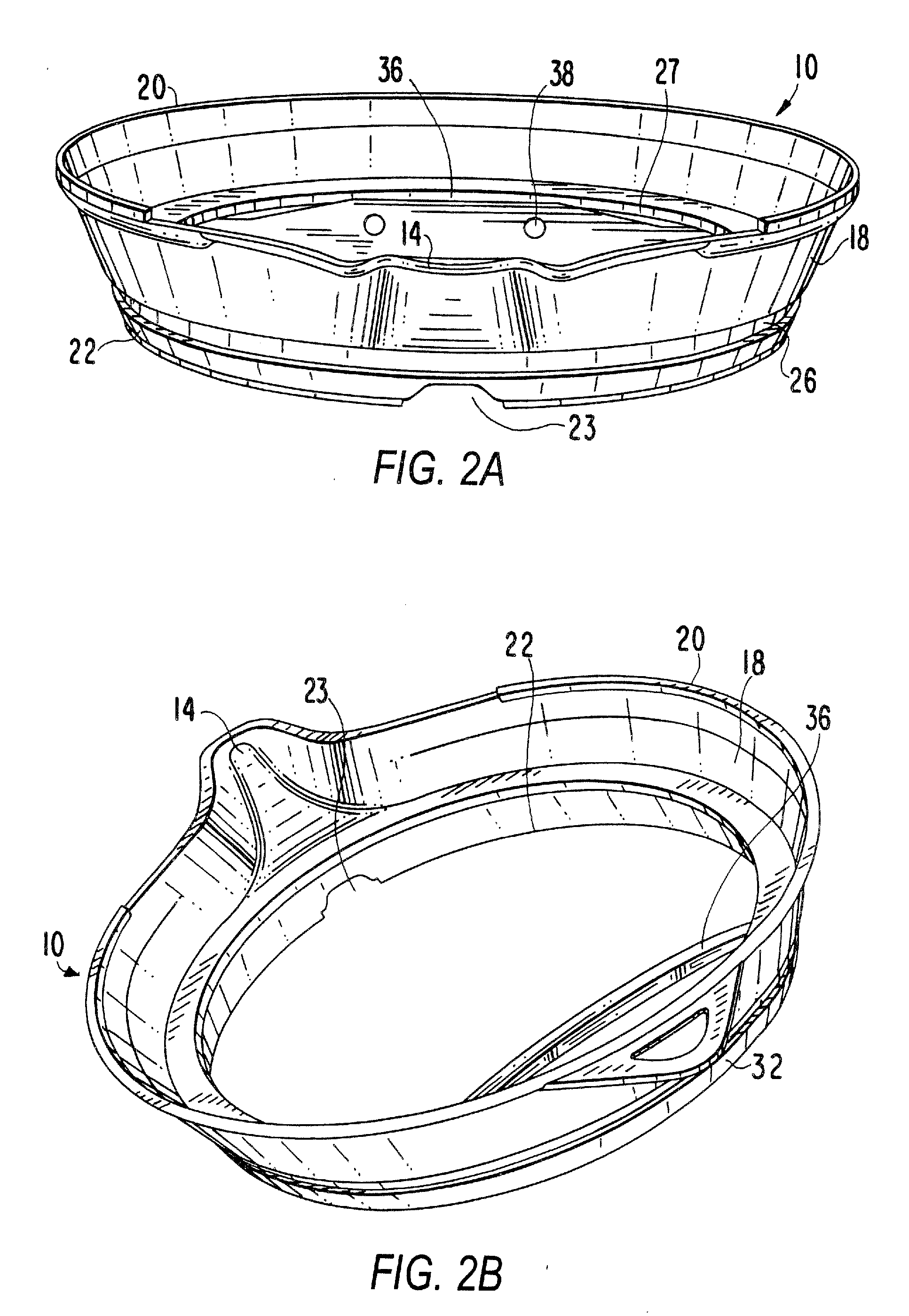
[0048] Referring to the drawings, FIG. 1 depicts a preferred embodiment of the inventive pouring spout (10) having a removable insert or lid (12). Each spout (10) also has a mouth (14), a central circular opening (16) and a lateral surface which forms a wall (18) having an upper edge or rim (20) and a lower edge or rim (22). Preferably, the lateral surface proceeds at an angle greater than ninety degrees from horizontal, such that the wall (18) that is formed inclines outwardly and upwardly from the center and lower edge (22) of the spout (10). Of course, the lateral surface may run at an angle that is ninety degrees or less from a horizontal surface of a container as well. In addition to forming the wall (18) of the spout (10), the lateral surface also forms a mouth (14). The mouth (14) extends outwardly beyond the perimeter of the wall (18) forming a channel out of which liquid is poured from its container. As the channel extends away from the center of the spout (10), it graduall...


PUM


Abstract

An inventive pouring spout that is selectively attachable to a container and fitted to the opening of the container with which it is used. In a preferred embodiment, the pouring spout is fitted to the dimensions of a one-quart container and includes a wall, a sealing member, a mouth and a handle. The handle is connected to the wall with a hinge that enables the handle to pivot away from the container to allow the sealing member to be appropriately positioned while the container rests flat on a surface. After the sealing member is in place, the handle is then pivoted back in position to securely hold the container. The handle includes a plurality of upwardly extending projections adapted to securely engage the bottom rim of the container. Furthermore, thermoplastic material is applied at the handle area forming a handle cover that is comfortable and easy to grip. Thermoplastic material is also preferably utilized in the construction of the sealing member for forming a seal between the spout and opening of the container.

Description

RELATED APPLICATION [0001] This application is a continuation-in-part application of application Ser. No. 11 / 356,776, filed on Feb. 17, 2006, which is a continuation-in-part application of application Ser. No. 10 / 830,275, filed on Apr. 22, 2004, now U.S. Pat. No. 7,134,576 and incorporated herein by reference.FIELD OF INVENTION [0002] This invention relates to a multifunction cover for containers, such as paint cans. More specifically, this invention involves a detachable pouring spout, optionally having a removable lid, which prevents the dripping and splashing of paint along the side and around the opening of a paint can. Furthermore, this invention involves, as another embodiment, a detachable pouring spout with handle which allows a user to easily hold on to a can of paint. Moreover, this invention involves, as yet another embodiment, a detachable pouring spout with handle, wherein the handle includes a hinge that allows the handle to pivot or otherwise move toward and / or away f...

Claims


Application Information

Patent Timeline
Patent Type & Authority Applications(United States)
IPC IPC(8): A47G19/14B65D5/72B65D25/40B65D25/00B44D3/12
CPCB44D3/127B44D3/128B65D25/48B65D25/2829B44D3/14
Inventor GRINGER, DONALDCHENG, YUAN FANG
Owner ALLWAY TOOLS
Why Eureka
Try Eureka