Conductive pipe and pipe connector assembly thereof

a technology of conductive pipes and connectors, which is applied in the direction of hose connections, pipe joints, mechanical equipment, etc., can solve the problems of leakage problems, lower operation efficiency, and high temperature, and achieve the effect of preventing leakage problems

Inactive Publication Date: 2007-12-27
COOLER MASTER CO LTD
View PDF17 Cites 6 Cited by
  • Summary
  • Abstract
  • Description
  • Claims
  • Application Information

AI Technical Summary

Benefits of technology

[0008]Yet another object of the invention is to provide a pipe connector to be used on a liquid cooling apparatus and a liquid conveying pipe to connect the coolant conveying pipe and the liquid cooling apparatus together. The pipe connector includes a connection member and a coupling member. The connection member has a connecting portion at one end and the other end fastened to the liquid cooling apparatus. Thereby a conductive pipe with an expanded portion at one end can be fastened to the connecting portion of the connection member, and the conductive pipe can be connected to the liquid cooling apparatus. As a result, the conductive pipe can be connected to the liquid cooling apparatus without soldering, and the leakage problem can be prevented.

Problems solved by technology

Electronic devices generate heat during operation that results in a higher temperature and a lower operation efficiency.
But liquid cooling apparatus also has drawbacks, such as installation and disassembly are more difficult, and the coolant has the leakage problem.
Air cooling cannot meet heat dissipation requirement.
Liquid cooling apparatus tend to generate leakage problem at the coupling portion between the delivery pipe and the cooling unit or radiation unit.
The rubber hose is prone to aging and deformation.
As a result, coolant tends to leak out through the coupling sleeve and the rubber hose.
And electronic elements could be short circuit and damaged.
Soldering increases fabrication process and results in a higher cost.
Moreover, soldering also tends to cause flow back of soldering paste that could result in leaking of the coolant.
This causes a great damage to electronic equipment.

Method used


Image

  • Conductive pipe and pipe connector assembly thereof
  • Conductive pipe and pipe connector assembly thereof
  • Conductive pipe and pipe connector assembly thereof

Examples


Embodiment Construction

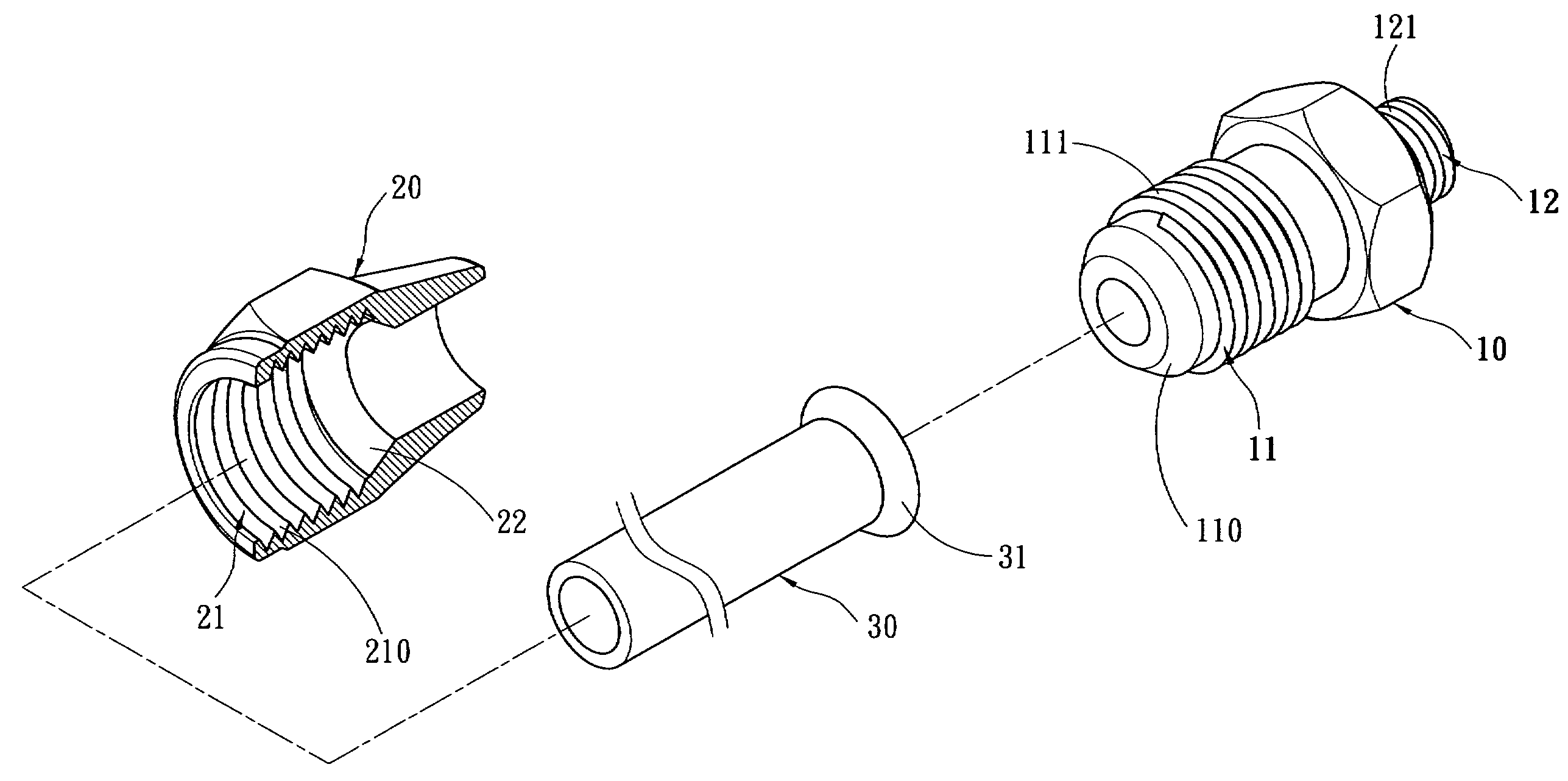
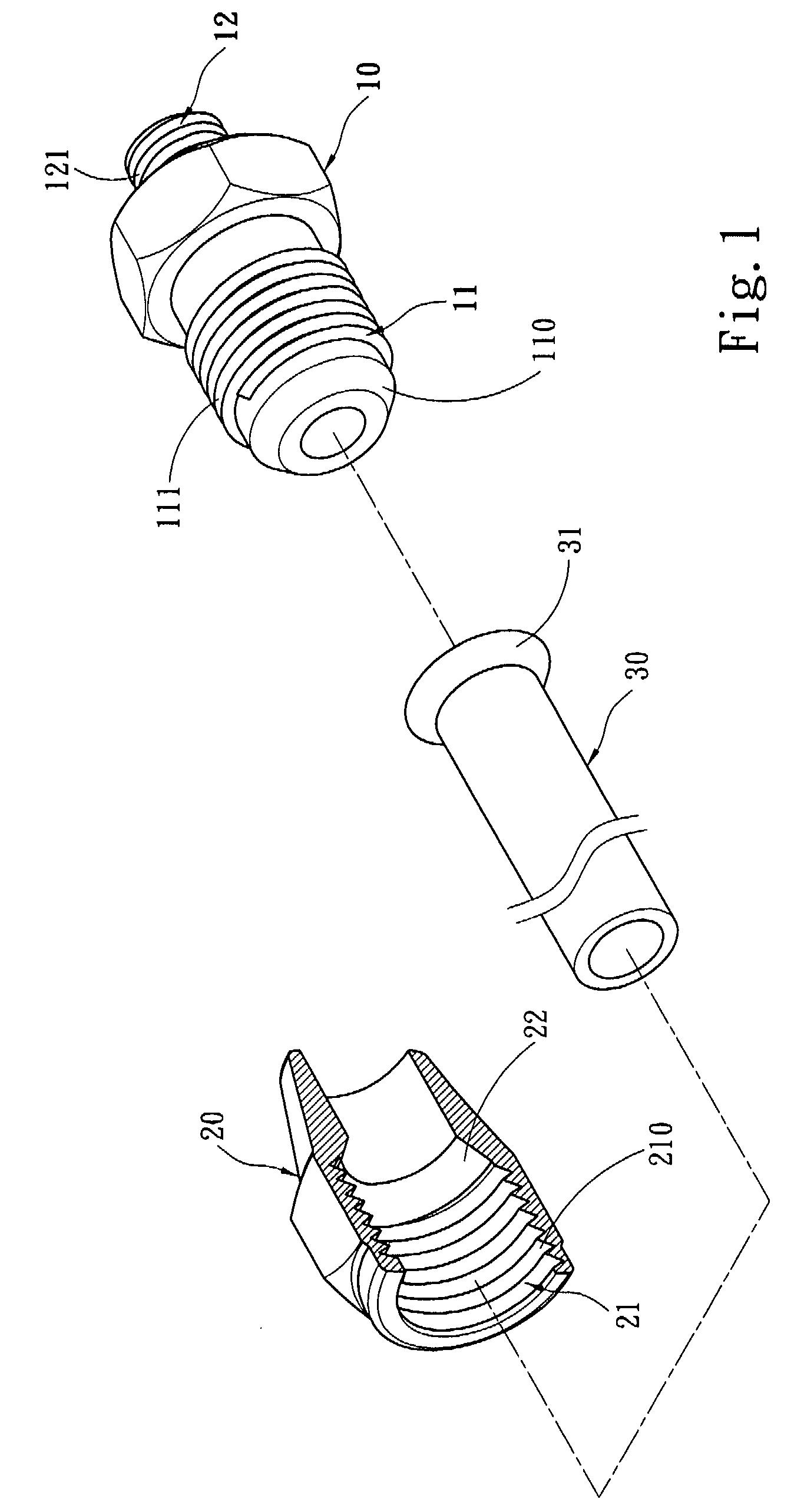
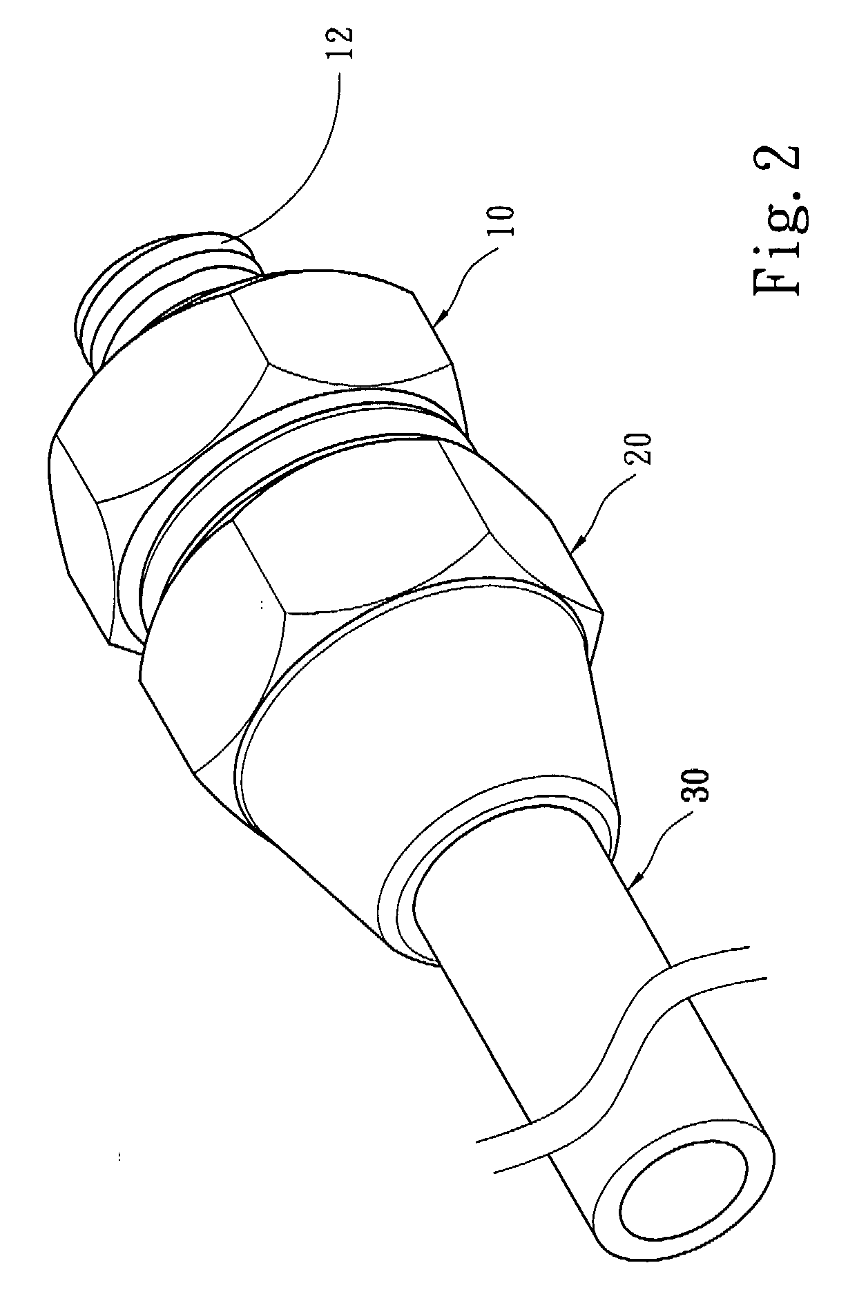
[0015]Please refer to FIGS. 1, 2 and 3, the invention includes a connection member 10, a coupling member 20 and a hard conductive pipe 30 which has at least an expanded portion 31 at one end.

[0016]The connection member 10 is a tubular element, and has at least a connecting portion 11 which has a chamfered angle 110 at one end to be tightly coupled with the expanded portion 31 of the conductive pipe 30. More specifically, the expanded portion 31 is substantially formed like a trumpet to couple with the chamfered angle 110 at one end of the connecting portion 11. The coupling member 20 also is a tubular element, and has at least one coupling portion 21 to be coupled with the connecting portion 11 of the connection member 10. The coupling member 20 has a chamfered surface 22 inside the tube. When the coupling member 20 and the connection member 10 are coupled together, the expanded portion 31 is forcefully fastened to the chamfered angle 110 of the connection member 10. Thus liquid or ...


PUM


Abstract

A conductive pipe and a pipe connector assembly include a connection member, a coupling member and a hard conductive pipe which has at least one expanded portion at one end. The connection member is a tubular element and has at least one connecting portion which has a chamfered angle at one end to be tightly coupled with the expanded portion. The coupling member also is a tubular element and has at least a coupling portion to be coupled with the connecting portion and a chamfered surface in the tubular interior. When the connection member and the coupling member are coupled together, the expanded portion is tightly coupled with the chamfered angle. The pipe connector may be used on a liquid cooling apparatus and/or a liquid conveying pipe thereof to connect any two conductive pipes or connect the conductive pipe with a liquid cooling apparatus.

Description

FIELD OF THE INVENTION[0001]The present invention relates to a conductive pipe and a pipe connector assembly thereof and particularly to a conductive pipe to connect two pipes that have an expanded portion at one end or to connect a conductive pipe with a liquid cooling apparatus and a pipe connector assembly thereof.BACKGROUND OF THE INVENTION[0002]Electronic devices generate heat during operation that results in a higher temperature and a lower operation efficiency. There are many methods to lower the temperature. Using a thermal medium to perform heat exchange is one of them. The thermal medium may be gas or liquid. A complex cooling apparatus could use two types of thermal media. For instance use coolant (such as water or coolant) to perform heat exchange with electronic elements to absorb heat generated by the electronic elements, then use cooling air or air fans to dispel the heat absorbed by the coolant to the atmosphere.[0003]Liquid has a better cooling effect (liquid coolin...

Claims


Application Information

Patent Timeline
Patent Type & Authority Applications(United States)
IPC IPC(8): F16L25/00
CPCF16L25/0072F16L19/0283
Inventor HUANG, TSUNG-CHENG
Owner COOLER MASTER CO LTD
Why Eureka
Try Eureka