Device for conducting air in order to provide air conditioning for a body support device

Inactive Publication Date: 2007-12-27
W E T AUTOMOTIVE SYST AG
View PDF16 Cites 51 Cited by
  • Summary
  • Abstract
  • Description
  • Claims
  • Application Information

AI Technical Summary

Benefits of technology

[0003] One object of the invention is a device with the features of claim 1. This has the advantage that through the i

Problems solved by technology

Integrating both systems into a seat is problematic.
This leads to overdimensioned pumps and low adjustment speeds.
Con

Method used


Image

  • Device for conducting air in order to provide air conditioning for a body support device
  • Device for conducting air in order to provide air conditioning for a body support device
  • Device for conducting air in order to provide air conditioning for a body support device

Examples


Embodiment Construction

[0008] A body support device is understood below to include, in particular, any furniture for sitting and / or resting and all devices offering support to a person while standing, sitting, or lying down in vehicles.

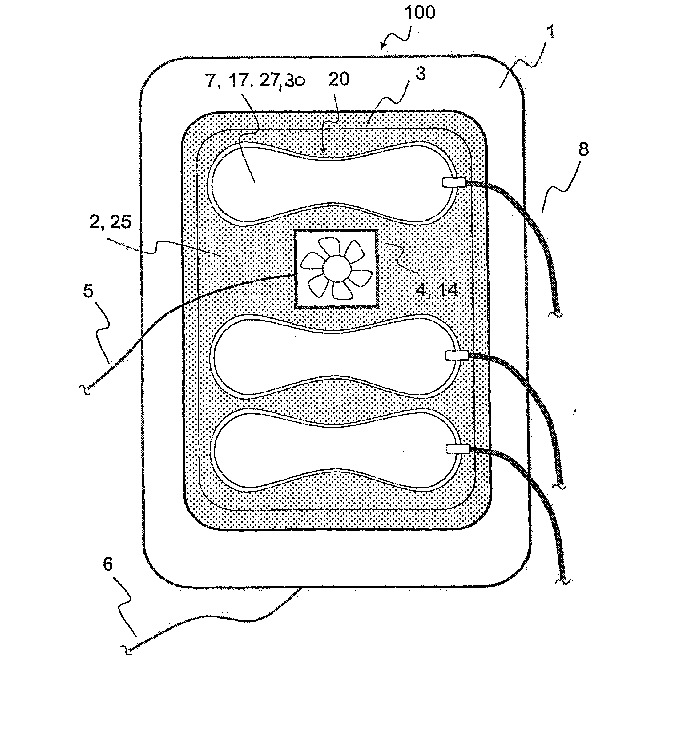
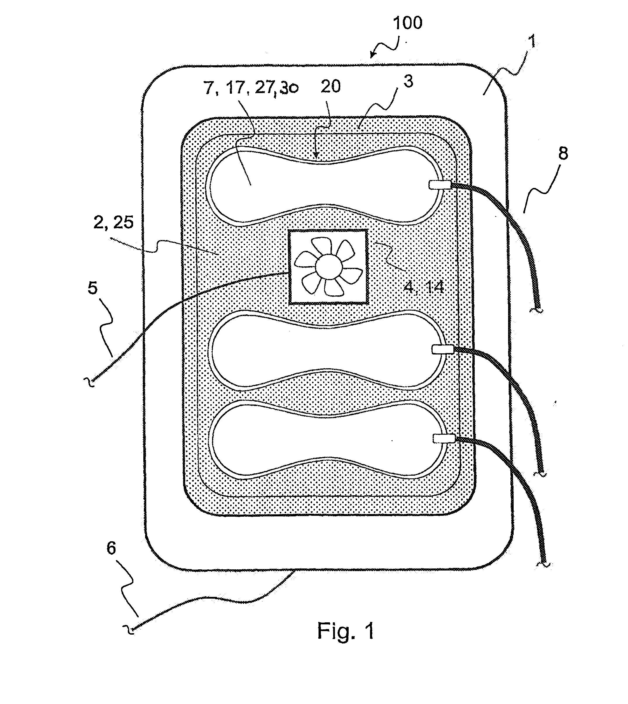
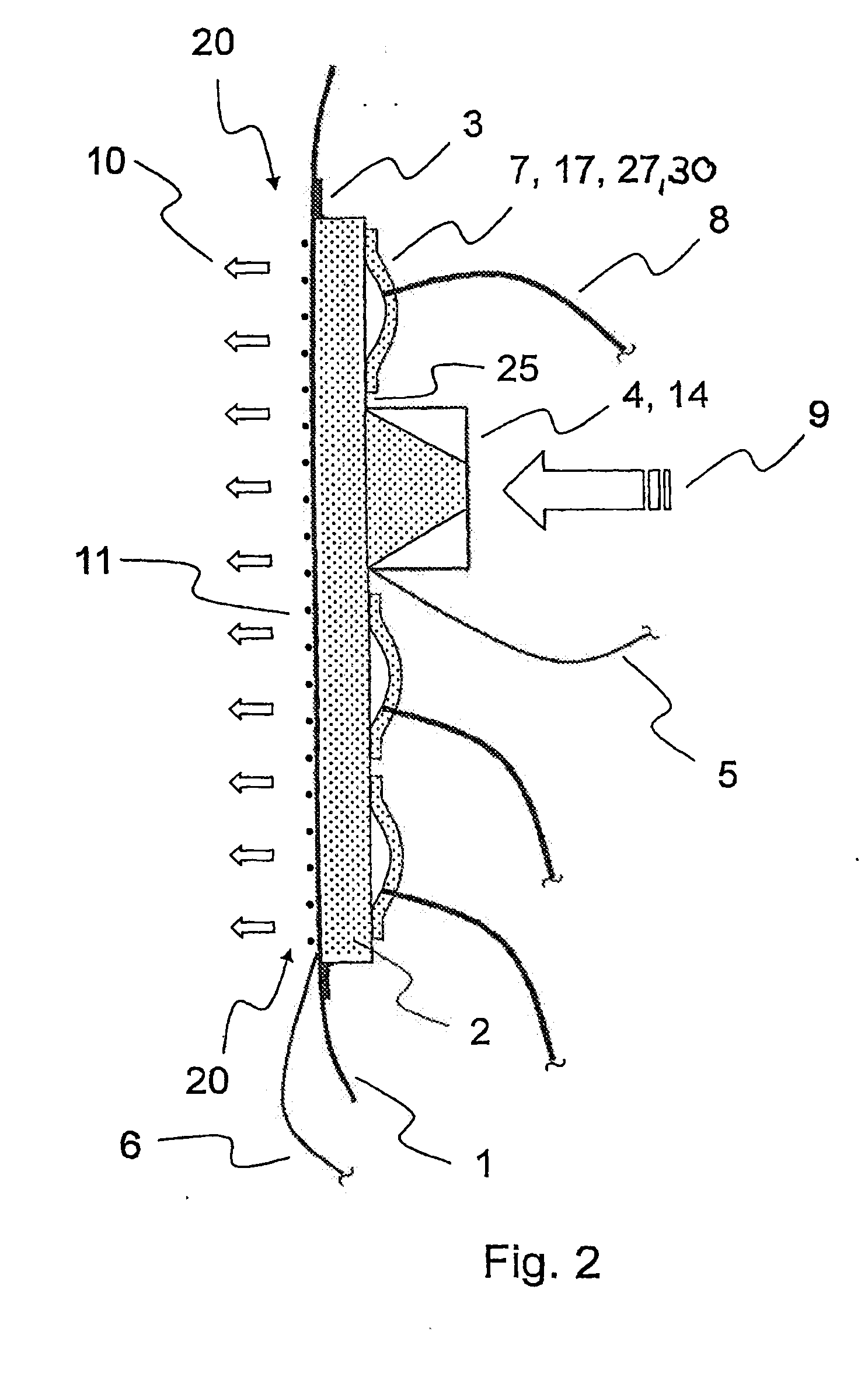
[0009]FIGS. 1 and 2 show a functional module according to the invention. A device 100 for guiding air for air conditioning a body support device has a carrier layer 1. This is manufactured from an air-permeable material. In the embodiment, it is formed at least partially by a non-woven material. It is designed for overlay on a foam core of a cushion, especially of a vehicle seat.

[0010] On the side of the carrier layer 1 facing a contact zone 20 and a user there are heating conductors 11 of an electrical heating element. They are arranged essentially over the entire surface of the carrier layer 1. They can be produced from metal and / or from electrically conductive plastics, e.g., carbon.

[0011] An air-guiding layer 2 is arranged on the side of the carrier layer 1 facing aw...


PUM


Abstract

The invention relates to a device (100) for conducting air in order to provide air conditioning for a body support device, particularly one in a vehicle seat. According to the invention, the device (100) is also provided with at least one adjustment device (7) for adjusting at least one contact area (20) of the body support device that comes into contact with a user.

Description

[0001] The present invention relates to a device for guiding air according to the preamble of claim 1. Devices according to the class are used, e.g., for air conditioning vehicle seats. STATE OF THE ART [0002] Air-conditioning devices for vehicle seats are known. Pneumatic seat adjusters for lumbar support and massage systems for seats are also known. Integrating both systems into a seat is problematic. If a seat adjuster is positioned under a seat cushion, large volumes must be moved in order to notice an effect at the seat surface. This leads to overdimensioned pumps and low adjustment speeds. Conversely, the air-conditioning function is impaired when the adjustment elements are positioned on the sitting surface. OBJECT OF THE INVENTION [0003] One object of the invention is a device with the features of claim 1. This has the advantage that through the integration of a seat adjuster into an air-conditioning device, mutual interference between the two systems is avoided. [0004] Othe...

Claims


Application Information

Patent Timeline
IPC IPC(8): A47C31/00
CPCA47C7/74
Inventor KROBOK, MARTINKOPFER, MARKUS
Owner W E T AUTOMOTIVE SYST AG
Why Eureka
Try Eureka