Method and system for image stabilization

a technology of image stabilization and image, applied in the field of image stabilization, can solve the problems of motion blur, degradation of the formed image, and almost impossible to avoid unwanted camera motion during a reasonably long exposure or integration time,

Active Publication Date: 2007-12-27
CORE WIRELESS LICENSING R L
View PDF7 Cites 28 Cited by
  • Summary
  • Abstract
  • Description
  • Claims
  • Application Information

AI Technical Summary

Benefits of technology

[0037]Alternatively, the imaging system further comprises an electronic circuit operatively connected to the image sensor for preventing the image sensor from attaining an exposure when the movement amount is outside the predetermined movement range. The electronic circuit can provide a signal to indicate whether the movement amount is within the predetermined movement range so as to allow the image sensor to attain said one or more exposures only when the movement amount is within the predetermined range.
[0041]It is possible that a light shutter is used for preventing the projected image from reaching the image sensor when the movement amount is out of the predetermined movement range.

Problems solved by technology

The problem of image stabilization dates back to the beginning of photography, and the problem is related to the fact that an image sensor needs a sufficient exposure time to form a reasonably good image.
Any motion of the camera during the exposure time causes a shift of the image projected on the image sensor, resulting in a degradation of the formed image.
Using one or both hands to hold a camera while taking a picture, it is almost impossible to avoid an unwanted camera motion during a reasonably long exposure or integration time.
Motion blur is particularly easy to occur when the camera is set at a high zoom ratio when even a small motion could significantly degrade the quality of the acquired image.
One of the main difficulties in restoring motion blurred images is due to the fact that the motion blur is different from one image to another, depending on the actual camera motion that took place during the exposure time.
1. Difficulty to avoid unwanted motion during the integration time when using a small hand-held device (like a camera phone).
2. The need for longer integration times due to the small pixel area resulting from the miniaturization of the image sensors in conjunction with the increase in image resolution. The smaller the pixel area the fewer photons per unit time could be captured by the pixel such that a longer integration time is needed for good results.
Consequently this approach might need quite expensive motion sensors (gyroscopes), which, apart of their costs, are also large in size and hence difficult to include in small devices.
In addition, if the exposure time is long then the position information derived from the motion sensor output exhibits a bias drift error with respect to the true value.
This error accumulates in time such that at some point may affect significantly the outcome of the system.
Actuator mechanisms are generally complex, which means that they are expensive and large in size.
The main problems in a typical multi-frame image stabilization solution include:1. Complex computation in image registration, and2. Moving objects in the scene: If there are objects in the scene that are moving during the time the image frames are acquired, these objects are distorted in the final image.

Method used


Image

  • Method and system for image stabilization
  • Method and system for image stabilization
  • Method and system for image stabilization

Examples


Embodiment Construction

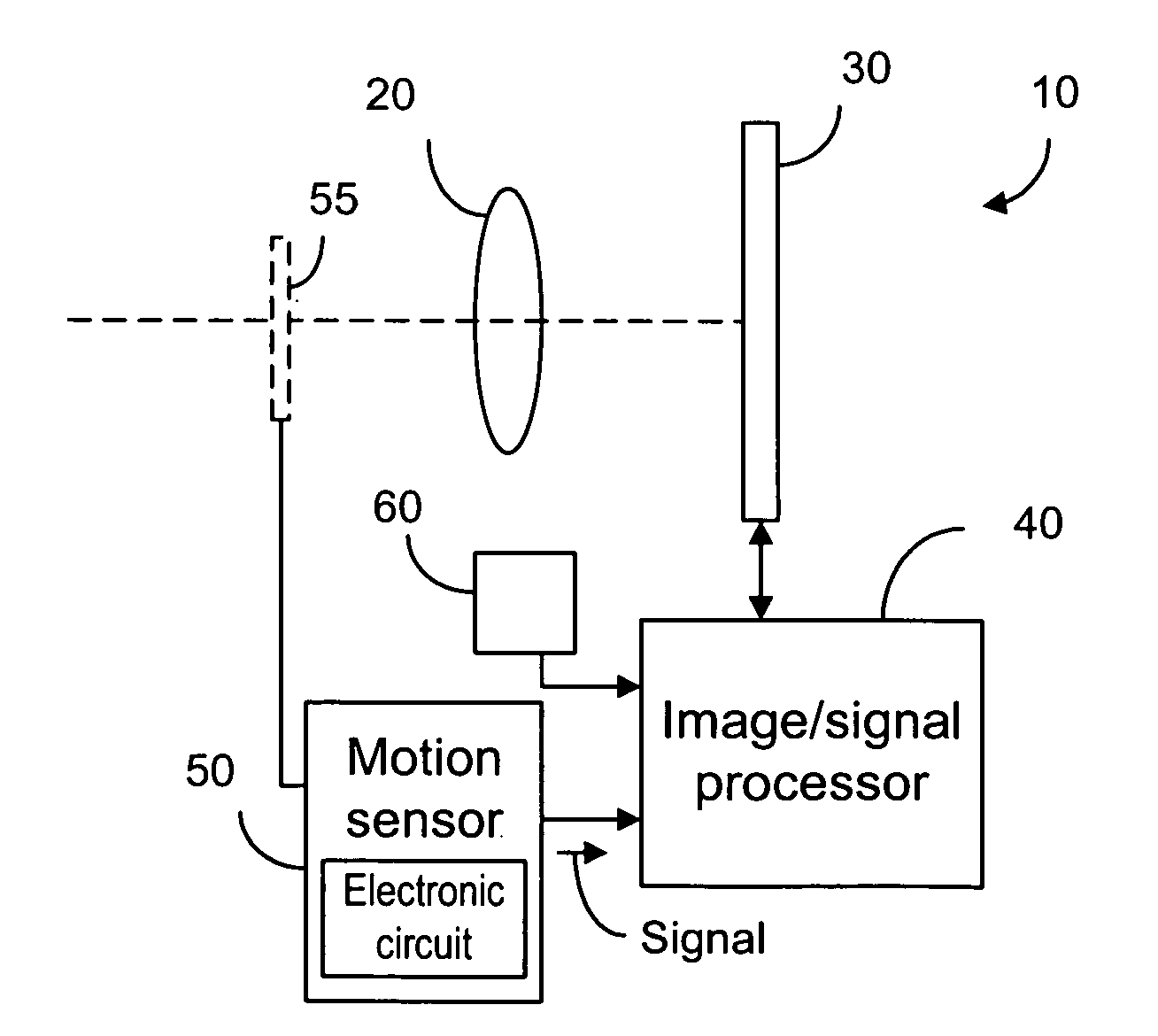
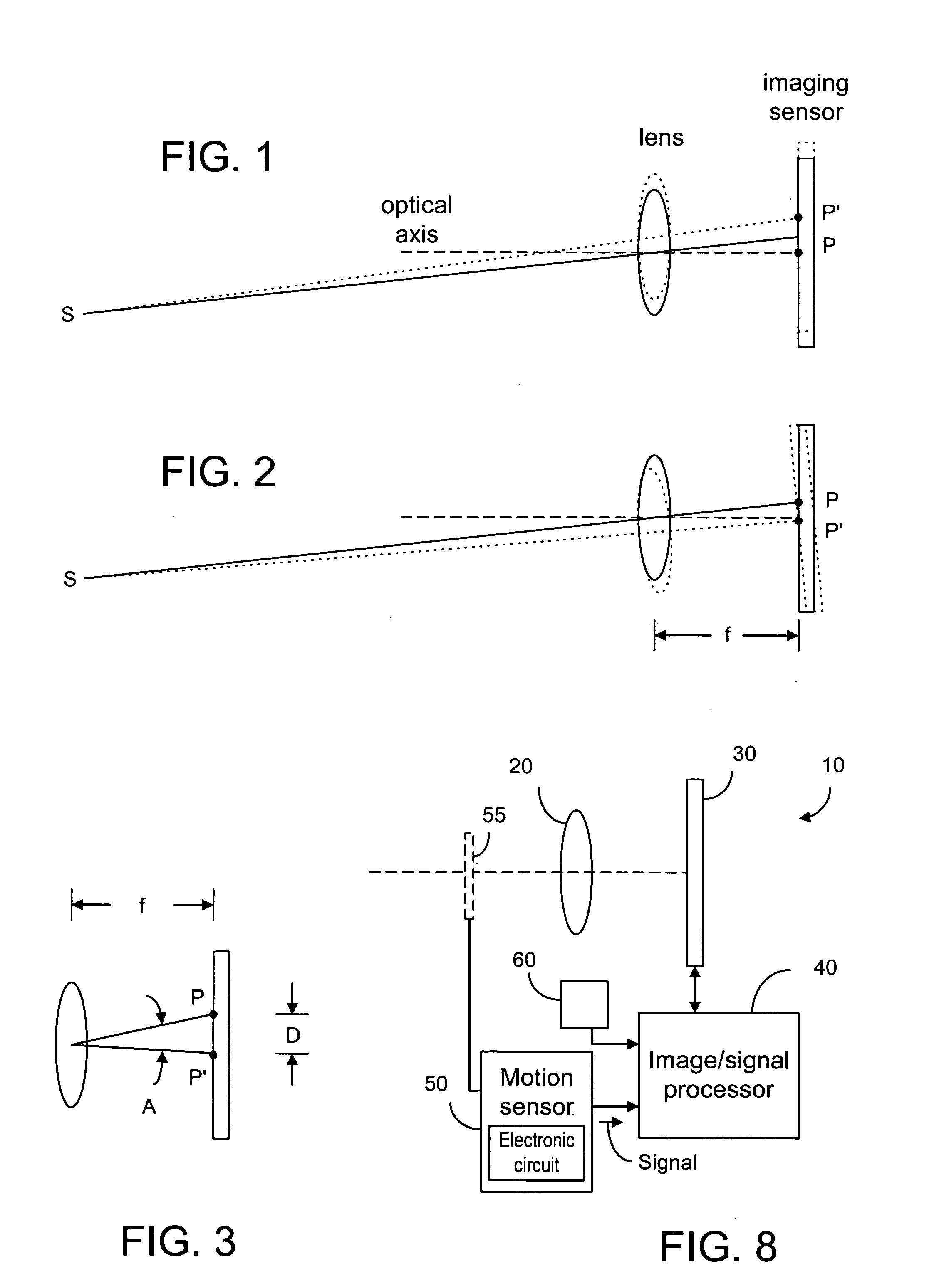
[0055]Using a small hand-held device, such as camera phone to take a picture, the movement of the device relative to a scene is most of the time unavoidable. If the exposure time is long, image blur occurs. Image blur is the result of the image shift in the image plane. As shown in FIG. 1, an image point P on the image sensor is shifted to point P′ due to a linear movement of the camera relative to a point S in the scene. FIG. 2 shows the image shift due to a rotational movement of the camera relative to point S. If the image shift distance, D, between point P and point P′ is larger than three or four pixels, then the image quality may be poor. Thus, it is desirable to limit the camera movement such that the image shift is within a predetermined range, say one or two pixels. The image shift distance not only varies with the camera movement, but also with the focal distance, f, between the image plane and the lens. In a camera with a zoom lens, the image shift distance is greater whe...


PUM


Abstract

A motion sensor is used to sense the movement of the camera during an exposure period. The camera has an image sensor to form one or more exposures. When the movement is within a certain range, the exposures are used to provide one or more frames so that an image can be constructed based on the frames. In one embodiment, the exposure period is divided into several short intervals in order to capture several image frames and only the image frames captured when the position of the camera is within a predetermined range are used to form the final image. The exposure time for each frame is small in order to reduce the motion blur degradation of the individual frames. If the camera is stable and substantially stationary relative to the scene, then all or many of the shorter frames are used to form the final image.

Description

FIELD OF THE INVENTION[0001]The present invention relates generally to image stabilization and, more particularly, to image stabilization by image processing.BACKGROUND OF THE INVENTION[0002]The problem of image stabilization dates back to the beginning of photography, and the problem is related to the fact that an image sensor needs a sufficient exposure time to form a reasonably good image. Any motion of the camera during the exposure time causes a shift of the image projected on the image sensor, resulting in a degradation of the formed image. The motion related degradation is called motion blur. Using one or both hands to hold a camera while taking a picture, it is almost impossible to avoid an unwanted camera motion during a reasonably long exposure or integration time. Motion blur is particularly easy to occur when the camera is set at a high zoom ratio when even a small motion could significantly degrade the quality of the acquired image. One of the main difficulties in resto...

Claims


Application Information

Patent Timeline
Patent Type & Authority Applications(United States)
IPC IPC(8): H04N5/228G03B5/00G03B7/00G03B7/091G03B9/58G03B15/00
CPCG03B7/00H04N5/23232H04N2007/145H04N5/23258H04N5/23277H04N5/23248H04N23/951H04N23/6845H04N23/68H04N23/6812
Inventor KAKKORI, HANNU
Owner CORE WIRELESS LICENSING R L
Why Eureka
Try Eureka