Method of making image capture unit

Inactive Publication Date: 2007-12-27
ETHER PRECISION
View PDF10 Cites 143 Cited by
  • Summary
  • Abstract
  • Description
  • Claims
  • Application Information

AI Technical Summary

Benefits of technology

[0006] The primary objective of the present invention is to provide a method of making an image

Problems solved by technology

As the requirement of decreasing the size of the image capture unit becomes more important, the size of all the optical elements must also decrease,but the barrel and the holder made by injection molding can not have the necessary precision in size.
In addition, an image receiving side of the image sensor is very sensitive and any fine dust on the image receiving side may cause

Method used


Image

  • Method of making image capture unit
  • Method of making image capture unit
  • Method of making image capture unit

Examples


Example

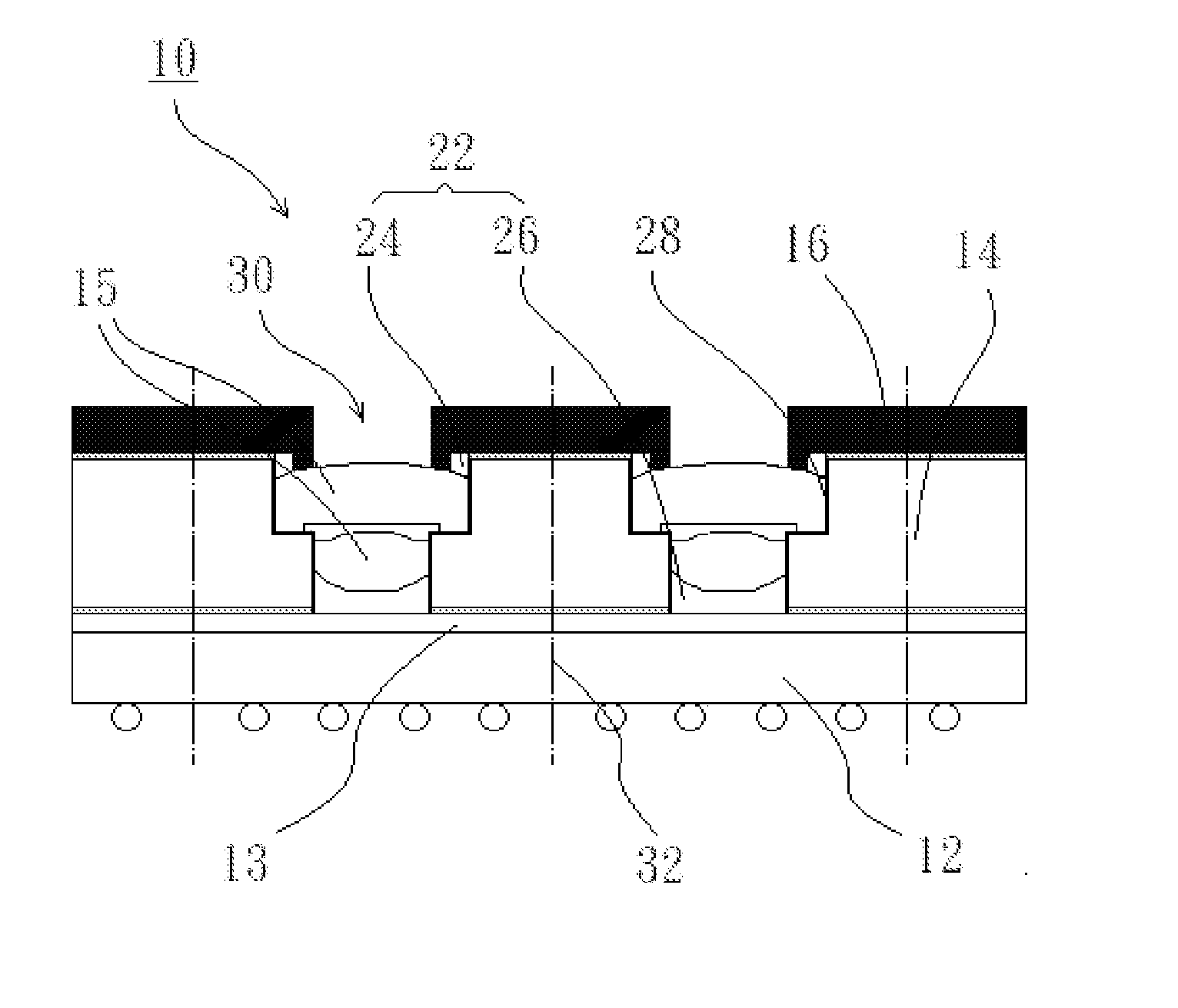
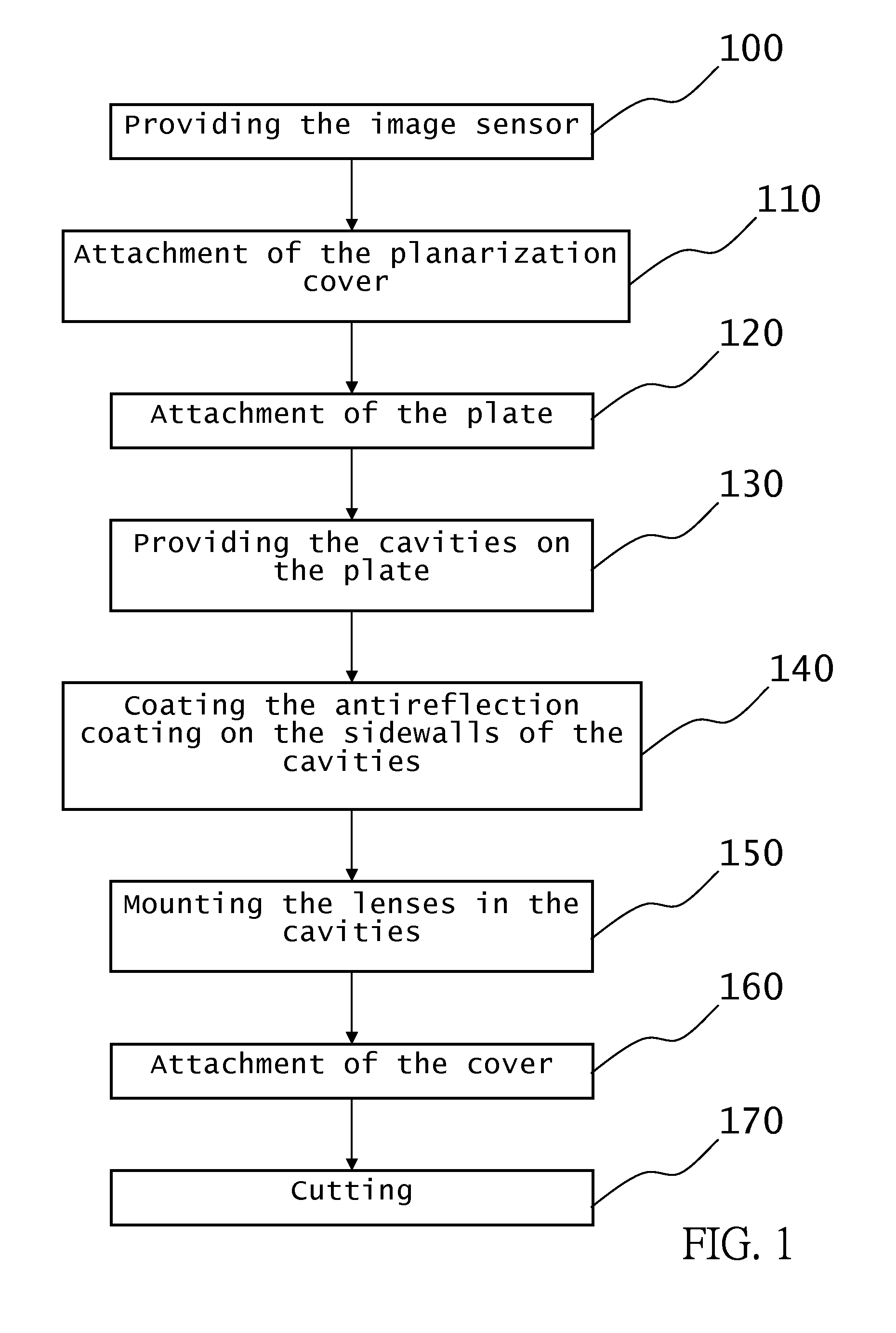
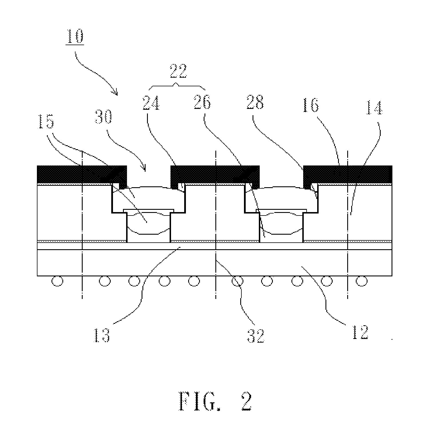
[0016] As shown in FIG. 1 and FIG. 2, a method of making an image capture unit 10 of the first preferred embodiment of the present invention includes the following steps:

[0017] The first step 100 is providing an image sensor 12. The image sensor 12 is a conventional CMOS or CCD sensor, which may have single sensing chip or multi sensing chips arranged in array (such as 2*2 or 2*3 array). In the present invention, the image sensor 12 may have a plurality of sensing chips arranged in array.

[0018] The second step 110 is attachment of a planarization cover 13. The planarization cover 13, which may be silicon oxide, silicon nitride, glass or other transparent materials, is provided on the image sensor 12 by the conventional planarization method. The planarization cover 13 may isolate moisture and dirt from the image sensor 12, and may act like an infrared radiation filter also to filter or select infrared radiation.

[0019] The third step 120 is attachment of plate 14. The plate 14, whi...


PUM


Abstract

The present invention provides a method of making an image capture unit, which includes the steps of: providing an image sensor; attaching a plate on the image sensor; providing at least one cavity on the plate aligned with the image sensor; mounting lenses in the cavity of the plate, and attaching a cover on the plate to shield a margin region of each of the lenses.

Description

BACKGROUND OF THE INVENTION [0001] 1. Field of the Invention [0002] The present invention relates generally to an optical lens, and more particularly to a method of making an image capture unit. [0003] 2. Description of the Related Art [0004] Typically, a conventional image capture unit includes an image sensor and an optical lens attached on the image sensor. The optical lens includes a holder, a barrel on the holder and one or more lenses mounted in the barrel. Typically, the barrel and the holder are made of plastic by injection molding that advantages mass production. As the requirement of decreasing the size of the image capture unit becomes more important, the size of all the optical elements must also decrease,but the barrel and the holder made by injection molding can not have the necessary precision in size. In addition, an image receiving side of the image sensor is very sensitive and any fine dust on the image receiving side may cause a mark on the image. In the conventio...

Claims


Application Information

Patent Timeline
IPC IPC(8): H04N5/225
CPCG02B7/021H01L27/14618H04N5/2257H04N5/2254H01L27/14625H01L2924/0002H04N23/57H01L2924/00
Inventor CHANG, CHAO-CHICHEN, YUNG-ILUSINCHI, JEAN-PIERRE
Owner ETHER PRECISION
Why Eureka
Try Eureka