

Optical disc recording method and optical disc recording apparatus
- Summary
- Abstract
- Description
- Claims
- Application Information
AI Technical Summary
Benefits of technology
Problems solved by technology
Method used
Image

Examples
embodiment 1
[0032]In the present embodiment, an example of an optical disc apparatus will be described in which power is changed according to the length of a mark to be recorded in a multi-pulse type strategy.
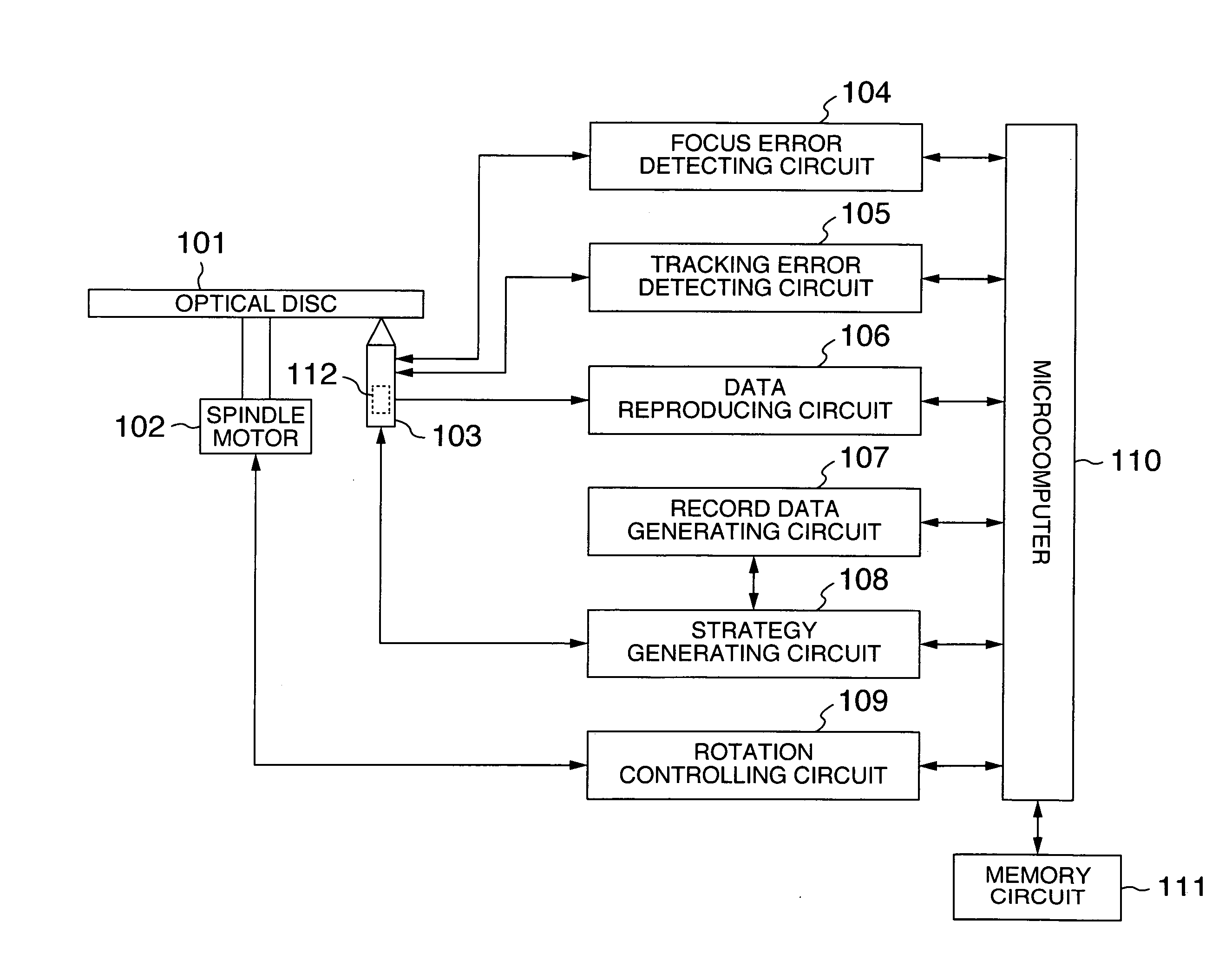
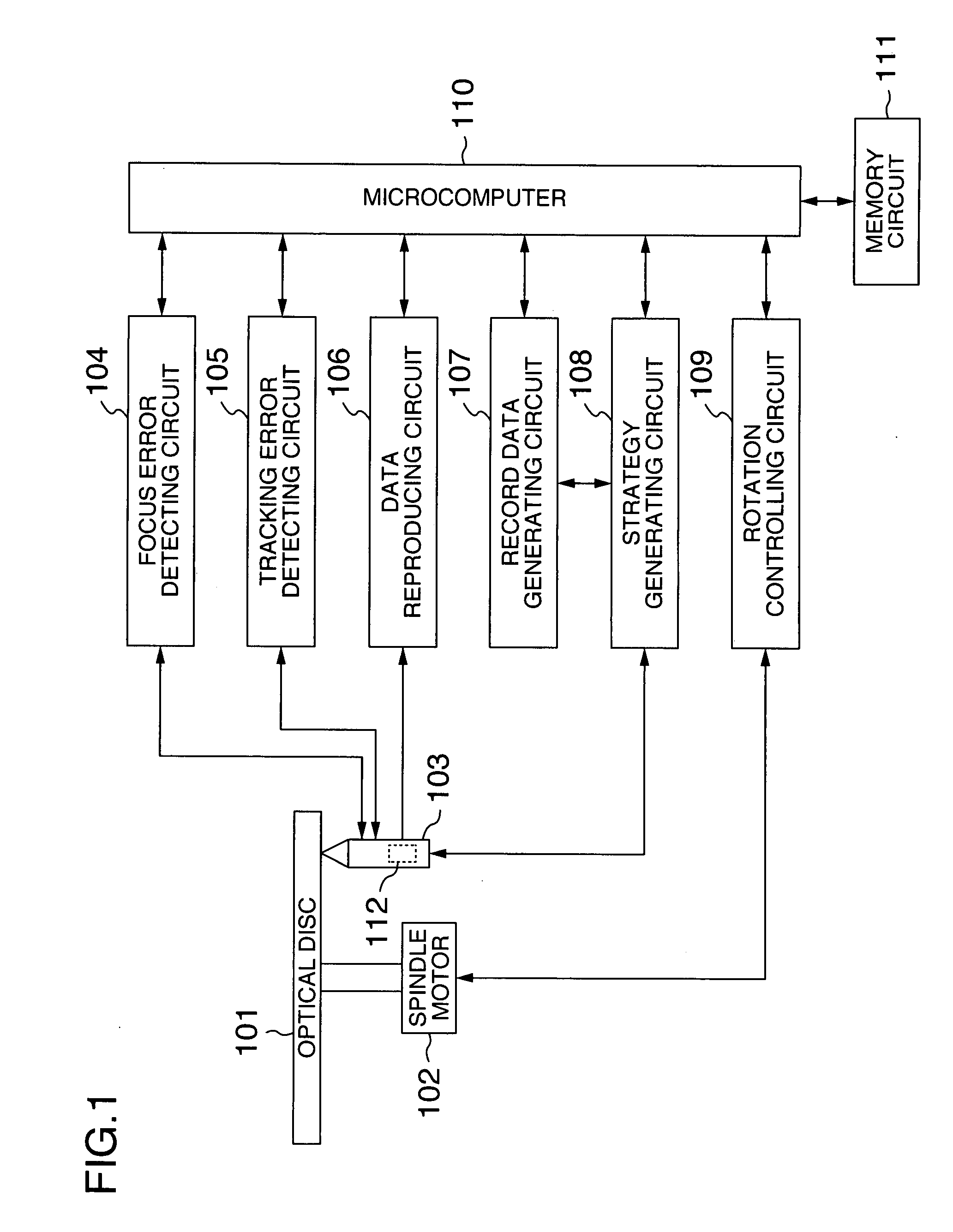
[0033]FIG. 1 is an exemplary block diagram of an optical disc recording and reproducing apparatus. In FIG. 1, 101 is an optical disc, 102 is a spindle motor, and 103 is an optical pickup. The optical pickup comprises a semiconductor laser, a lens group, a photodetector, a temperature sensor and the like. For the sake of simplicity, only the temperature sensor 112 is shown, with other components constituting the optical pickup being omitted in FIG. 1. It should be noted that, in order to make description more specific, the description is made on the assumption that the optical disc is a BD-RE.
[0034]First, a rotation speed, a radius position and the like are specified by a rotation controlling circuit 109, and the optical disc 101 is rotated at a desired rotation speed. A focus error signal ...
embodiment 2
[0051]In the present embodiment, an optical disc apparatus will be described in which power is changed according to the length of a mark to be recorded in a castle type strategy. While the BD-RE is used as a specific example of the optical disc in the embodiment 1, description will be made using a BD-R as a specific example in the present embodiment.
[0052]The structure of the optical disc apparatus, strategy generating circuit and the like is the same as that of the embodiment 1. Furthermore, as is the case with the embodiment 1, the timing computing circuit 301 determines the timing of the rising position, falling position and width of the top pulse and last pulse according to the length of the self mark length and lengths of the spaces before and after the self mark.
[0053]The strategy used in the present embodiment is a castle type. Therefore, unlike in the multi-pulse type, the intermediate pulse at the time when the length of the mark to be recorded is long takes a given interme...
embodiment 3
[0058]In the present embodiment, a variation example of the embodiment 1 and embodiment 2 will be described.
[0059]In the embodiment 1, when the length of the mark to be recorded is 3T or more, the same power is set to all of the top pulse, intermediate pulse and last pulse. However, the thermal interference between adjacent marks takes place mostly at the timing of inputting the first recording power to the mark to be recorded and at the timing of interrupting last recording power to the mark to be recorded. Therefore, in the present embodiment, only the recording power for the top pulse is set according to the length of the self mark. Specific setting of the recording power is as described in FIG. 4D. When the length of the mark to be recorded is 3T or more, only the recording power for the top pulse is controlled according to the length of the self mark, with the recording power for the intermediate pulse and last pulse being all set to a constant value (e.g. P5T). This enables th...
PUM
 Abstract
Description
Claims
Application Information