
Pulse shape modulation and information recording and reproducing technique using pulsed laser beam

a pulse shape and laser beam technology, applied in the field of pulse shape modulation and information recording and reproducing techniques, can solve the problems of preventing accurate reproduction of information from the disk, affecting the quality of the reproduced signal, etc., and achieve the effect of improving recording quality and less degradation

Inactive Publication Date: 2007-03-13
RICOH KK
View PDF15 Cites 2 Cited by
  • Summary
  • Abstract
  • Description
  • Claims
  • Application Information

AI Technical Summary

Benefits of technology

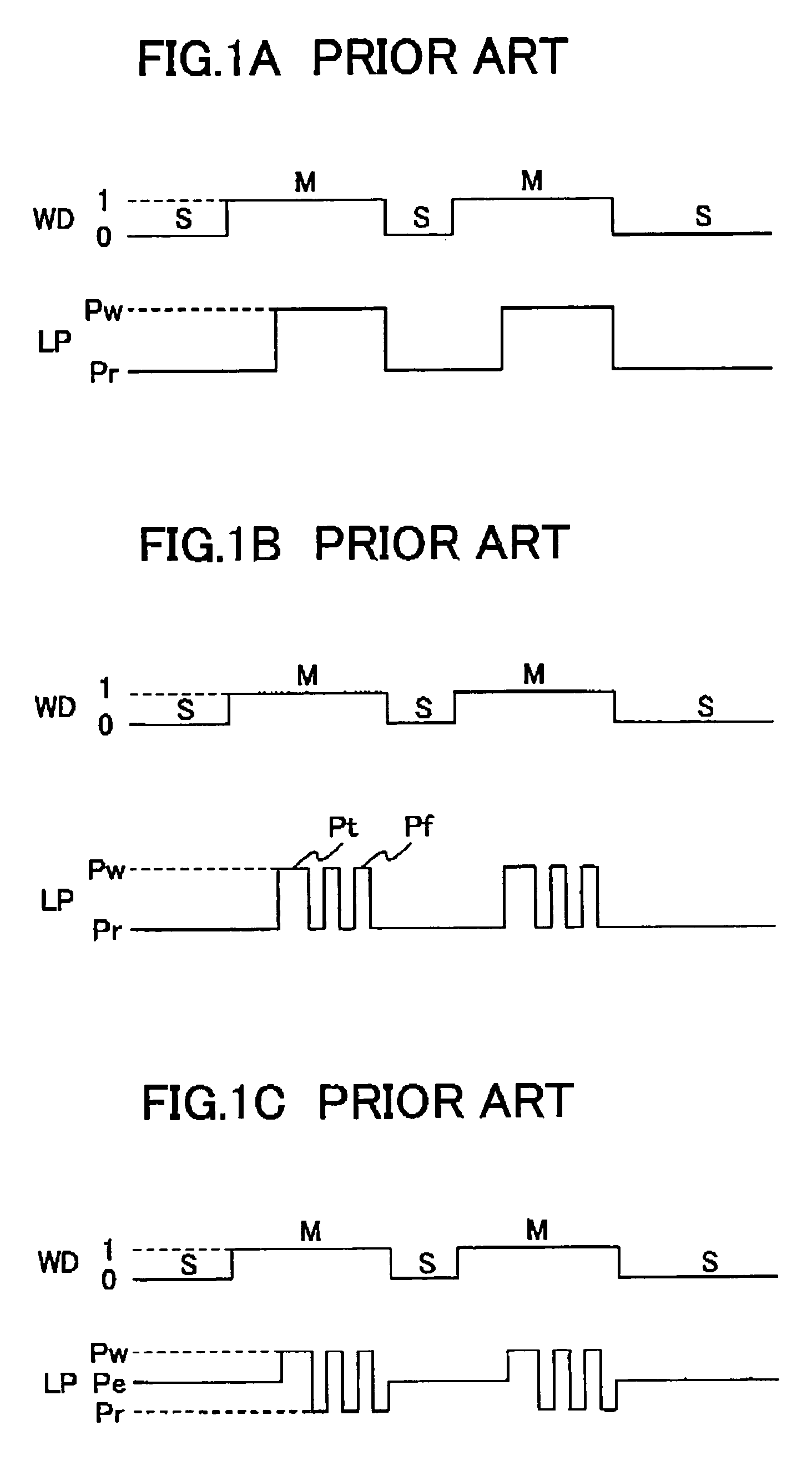
[0014]It is therefore an object of the present invention to overcome the above-described problem, and to provide a pulse shape modulation method for producing an optimum light emission pulse suitable for stable recording operations and achieving satisfactory recording quality.
[0015]It is another object of the present invention to provide an information recording / reproducing apparatus that can perform stable recording operations resulting in excellent recording quality.
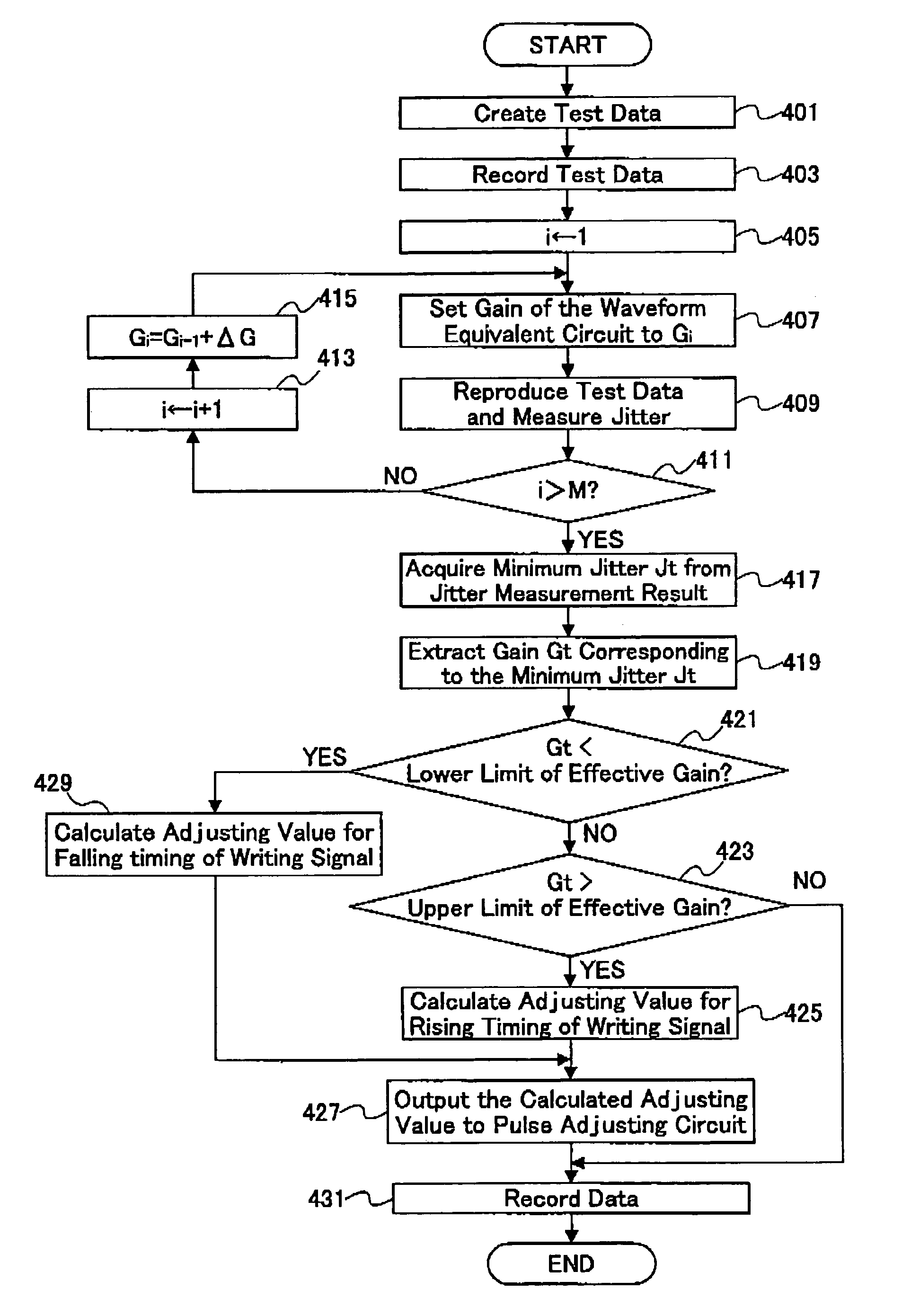
[0032]With this information recording and reproducing apparatus, when the amplitude modulation gain for the reproduced signal corresponding to the minimum jitter is not within the prescribed range, the pulse shape of the pulsed laser beam is modulated such that a satisfactory reproduced signal with lesser degradation is acquired in a stable manner. Since the recording operation is carried out using the pulse shape modulated laser beam, the recording quality can be improved.

Problems solved by technology

This causes the quality of the reproduced signal to vary, and prevents accurate reproduction of information from the disk.

Method used


Image

  • Pulse shape modulation and information recording and reproducing technique using pulsed laser beam
  • Pulse shape modulation and information recording and reproducing technique using pulsed laser beam
  • Pulse shape modulation and information recording and reproducing technique using pulsed laser beam

Examples


Embodiment Construction

[0046]The preferred embodiments of the present invention are described below with reference to the attached drawings.

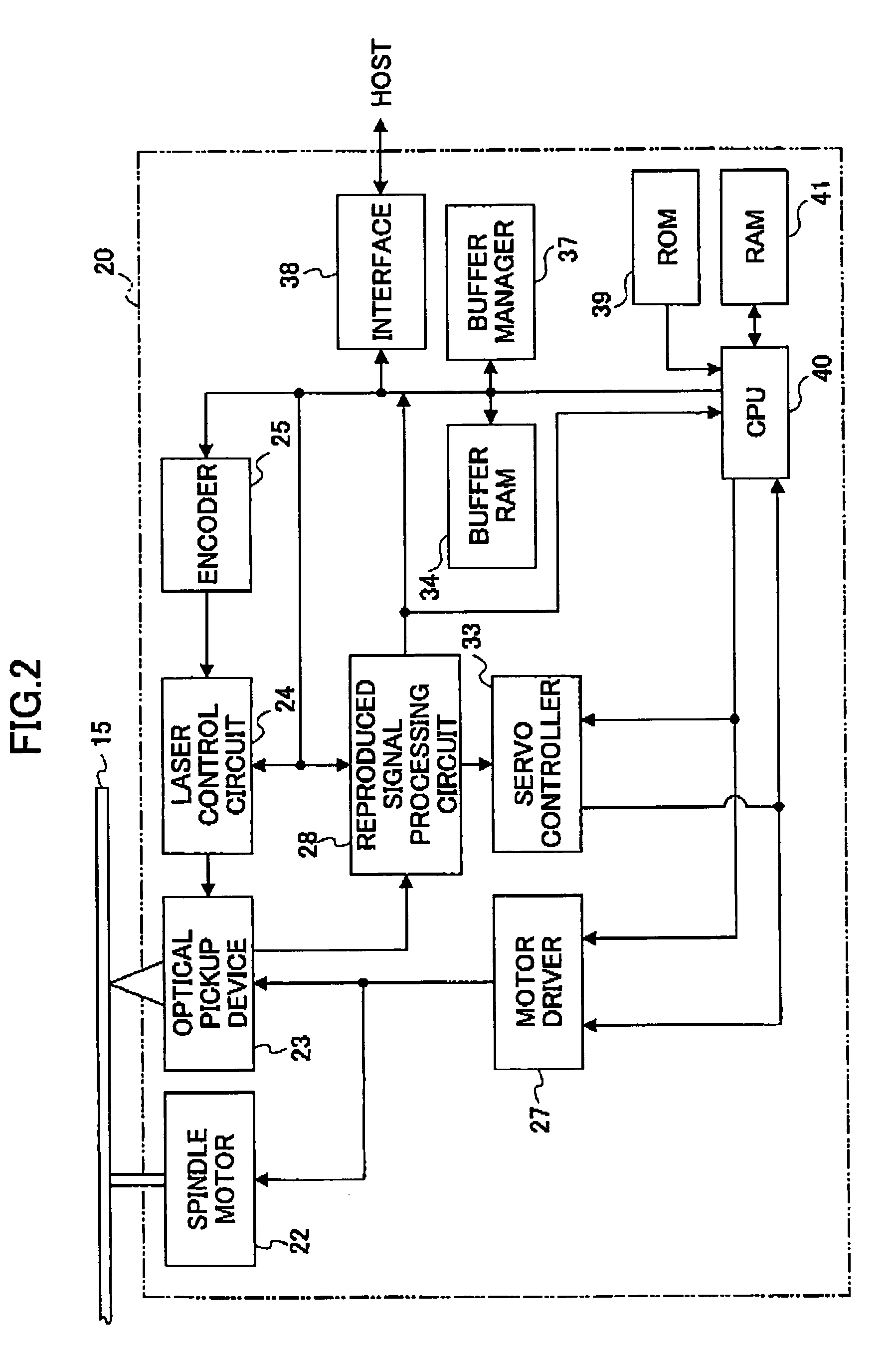
[0047]FIG. 2 is a block diagram of an optical disk apparatus, which functions as an information recording and reproducing apparatus, according to an embodiment of the invention.

[0048]The optical disk apparatus 20 shown in FIG. 2 includes a spindle motor 22 for rotating an optical disk 15, an optical pickup device 23, a laser control circuit 24, an encoder 25, a motor driver 27, a reproduced signal processing circuit 28, a servo controller 33, a buffer RAM 34, a buffer manager 37, an interface 38, a ROM 39, a CPU 40, and a RAM 41. In FIG. 2, the arrows indicate typical signal flows or data flows, but are not intended to depict all the connections between the respective blocks. In this embodiment, an information recording medium conforming to the DVD+R standard is used as the optical disk 15.

[0049]The optical pickup device 23 guides a laser beam onto the recording side ...


PUM


Abstract

In the disclosed pulse shape modulation method, an amplitude modulation gain for a reproduced signal from an information recording medium that makes the jitter of the reproduced signal become the minimum is specified. Then, it is determined whether the amplitude modulation gain corresponding to the minimum jitter resides within a prescribed range. If the amplitude modulation gain corresponding to the minimum jitter is outside the prescribed range, the pulse shape of the pulsed laser beam is modulated.

Description

BACKGROUND OF THE INVENTION[0001]1. Field of the Invention[0002]The present invention generally relates to pulse shape modulation and an information recording and reproducing technique, and more specifically, to a pulse shape modulating technique for modulating a pulse shape when recording and reproducing information in and from a data recording medium using a pulsed laser beam.[0003]2. Description of Related Art[0004]Remarkable progress of personal computer functionality in recent years has allowed the personal computer to process audio-visual information, such as music and video images. Since the data volume of such audio-visual information is very large, optical disks, such as compact disks (CDs) and digital versatile disks (DVDs) have been attracting attention as large-volume information recording media. As the cost and price of such optical disks are reduced, optical disk apparatuses for recording and reproducing information in and from optical disks are spreading among users, ...

Claims


Application Information

Patent Timeline
IPC IPC(8): G11B7/005G11B7/125G11B7/0045G11B7/1267
CPCG11B7/1267G11B7/00456
Inventor OGAWA, IPPEI
Owner RICOH KK
Learn More