
Thread-tapping screw

a technology of thread-tapping screw and screw head, which is applied in the direction of thread fasteners, screws, fastening means, etc., can solve the problems of screw being subject to wear as it is screwed, and the possibility of multiple use of thread-tapping screw cannot be predicted, so as to achieve high reliability of prediction of remaining load-bearing capacity

Inactive Publication Date: 2007-12-27
HILTI AG
View PDF9 Cites 25 Cited by
  • Summary
  • Abstract
  • Description
  • Claims
  • Application Information

AI Technical Summary

Benefits of technology

[0011] The at least one wear indication element shows degree of wear of the thread and, thereby, permits to determine load-carrying characteristics of a dismounted thread-tapping screw. The user can clearly and simply recognize if a load-bearing capacity of a dismounted thread-tapping screw fell below a predetermined threshold and whether the dismounted screw can be used anew or not. A multiple use of a thread-tapping screw permits to reduce costs and resources, e.g., associated with storage and logistics, in particular at temporary attachments.
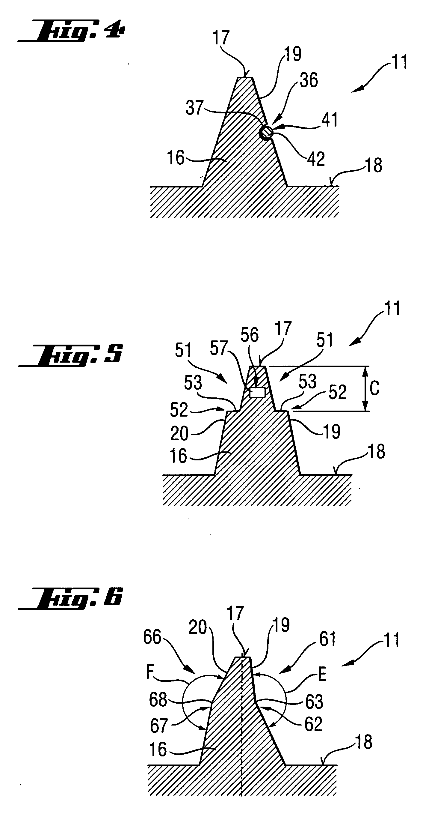
[0019] Advantageously, more than one wear indication elements are provided on a thread. The wear indication elements are located at different locations at a distance from each other so that more than one region of the thread can predict further use of the dismounted thread-tapping screw. Alternatively, several wear indication means are arranged at different distances from the rim of the thread flank, whereby not only the lower threshold of the load-bearing capacity of the thread-tapping screw but also an intermediate threshold are visually communicated to the user. Further, different kinds of wear indication elements can be provided on the thread of a thread-tapping screw, which insures a high reliability of prediction of remaining load-bearing capacity of the thread-tapping screw.

Problems solved by technology

The drawback of a conventional thread-tapping screw, in particular of that which is set in a mineral component, consist in that the screw is subjected to wear as it is being screwed in.
The degree of wear and, thus, wear of the thread flanks of the thread depends on local conditions in the constructional component, and the possibility of a multiple use of the thread-tapping screw cannot be predicted.

Method used


Image

  • Thread-tapping screw
  • Thread-tapping screw
  • Thread-tapping screw

Examples


Embodiment Construction

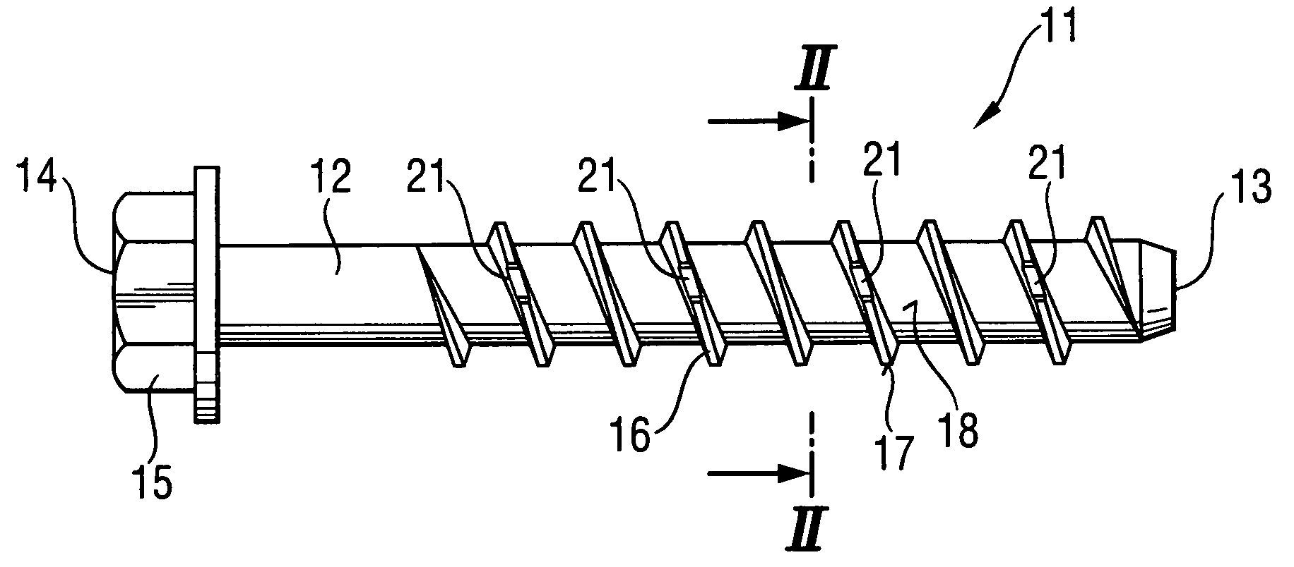
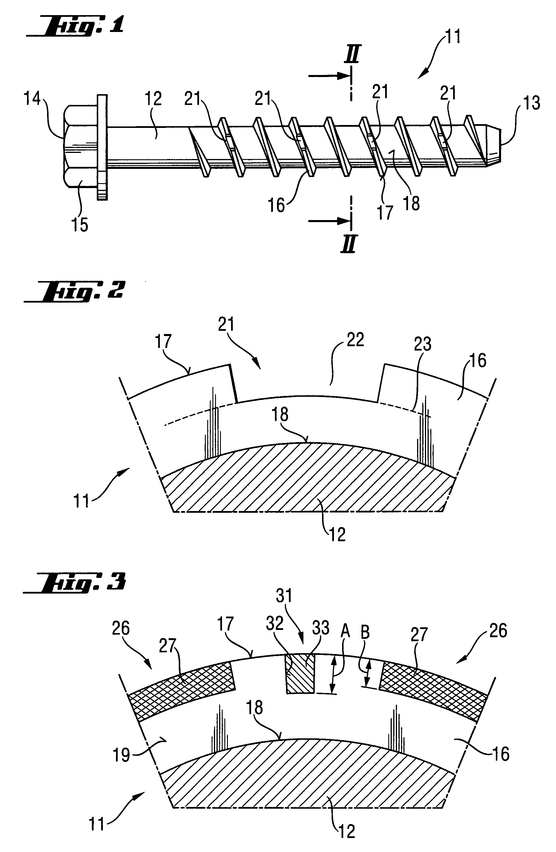
[0029] A thread-tapping screw 11 according to the present invention, which is shown in FIGS. 1-2, has a shaft 12 having opposite first 13 and second 14 ends. At the second end 14 of the shaft 12, there is provided load application means 15 in form of a hexagon head. The screw 11 further has a thread 16 extending regionwise over the length of the shaft 12. On the thread 16, there are provided several wear indication elements 21. The wear indication elements 21 are located in recesses 22 which extend from the rim 17 of the thread 16 to the thread root 18. When the regions of the thread 16 adjacent to the recess 22 wear off up to line 23 as a result of screwing of the thread tapping screw 11, e.g., in a mineral component, the recess 22 is not recognizable as such. Thereby, a visual signal is communicated to the user that the load bearing capacity of the thread tapping screw 11 fell below its lower threshold, and the screw should not be re-used any more for certain attachments.

[0030]FI...


PUM


Abstract

A thread-tapping screw has a shaft (12) with first (13) and second (14) ends, a load application element (15) provided at one of the first and second ends (13, 14), a thread (16) extending at least regionwise along the shaft (12), and at least one wear indication element (21, 26, 31; 36, 41; 51, 56; 61, 66) provided on the thread (16).

Description

BACKGROUND OF THE INVENTION [0001] 1. Field of the Invention [0002] The present invention relates to a thread-tapping screw including a shaft having first and second ends, load application means provided at one of the first and second ends, and a thread extending at least regionwise along the shaft. [0003] 2. Description of the Prior Art [0004] Screws with a self-tapping thread for different constructional components are well known. Thus, German Publication DE 33 01 414 A1 discloses a thread-tapping screw for a mineral constructional component, e.g., such as concrete and including a shaft having first and second ends, load application means provided at one of the first and second ends, and a thread extending at least regionwise along the shaft. [0005] The thread-tapping screw is screwed in a pre-drilled hole in a constructional component with an appropriate tool such as, e.g., a screw-driver, hammer drill, spanner and the like, with a front portion of the screw tapping a counter-thr...

Claims


Application Information

Patent Timeline
IPC IPC(8): F16B35/04
CPCF16B1/0071F16B25/00F16B25/0052F16B25/0047F16B25/0026F16B2200/95
Inventor WIESER, JUERGENDOBLER, JOHANNES
Owner HILTI AG
Learn More