Fitting for a vehicle seat

a vehicle seat and seat technology, applied in the field of vehicle seats, can solve the problems of increasing the necessary operating force, and achieve the effects of increasing the operating force, reducing the operating force, and increasing friction

Inactive Publication Date: 2007-12-27
KEIPER GMBH & CO KG
View PDF12 Cites 3 Cited by
  • Summary
  • Abstract
  • Description
  • Claims
  • Application Information

AI Technical Summary

Benefits of technology

[0005] Because the rotating driver impinges on the rotatable running eccentric without lateral force (relative to a common axis of rotation), the driving torque of the driver is applied coaxially to the running eccentric, so that a movement may be carried out under the same frictional conditions. A tipping movement about an instantaneous center of rotation triggered by lateral forces and overriding the rotation, which would lead to a local increase in friction and thus to increased operating forces, is avoided. The required freedom from lateral forces may therefore be understood such that minimal lateral forces which are required, for example, by component tolerances, are allowed, as long as they do not substantially alter the friction.
[0006] The impingement without lateral force is, for example, achieved by the contact points between the driver and the running eccentric being distributed uniformly over the periphery and being at the same distance from the common axis of rotation of the driver and of the running eccentric. In an embodiment with slot-pin-guides, which offers the advantage of idle motion to determine the time sequence of the control of the locking eccentric and the running eccentric, for example two pins and two elongated holes are arranged point symmetrically to one another relative to the axis of rotation of the driver and the running eccentric. Any association of pins and elongated holes to the driver on the one hand and to the running eccentric on the other hand is possible. It is, however, also possible to provide a rotationally fixed connection between the driver and the running eccentric, for example by the contact points—preferably defined by pins and holes—being configured without play. The rotationally fixed connection may, therefore, be developed such that the driver and the running eccentric form a single component, i.e. the driver is configured as (e.g., comprises) a running eccentric.
[0007] Because the running eccentric is mounted by way of rolling-contact bearing bushings or plain bearing bushings, both relative to the first fitting part and also relative to the second fitting part, a small amount of friction may be selected (e.g., may exist) between the running eccentric and the rolling-contact bearing bushing or plain bearing bushing (or between a rolling-contact bearing bushing or plain bearing bushing and the associated fitting part) which is less than the friction between the locking eccentric and at least one of the fitting parts, required to lock the fitting. This reduces the operating forces. The locking eccentric serves for locking the fitting and the positioning without play. With regard to the geometry, the bearing of the running eccentric against the rolling-contact bearing bushing or plain bearing bushing is carried out radially outwardly and radially inwardly relative to the axis of rotation thereof. Preferably, each of the two rolling-contact bearing bushings or plain bearing bushings may be connected fixedly in terms of rotation to the fitting associated therewith, for example pressed into an aperture or a collar or pressed onto a collar. Alternatively, one (or both) of the two rolling-contact bearing bushings or plain bearing bushings may be connected fixedly in terms of rotation to the running eccentric, for example pressed into or onto the running eccentric.

Problems solved by technology

By the choice of materials and the shape of the components, increased friction may occur locally during the adjusting movement, which increases the necessary operating forces.

Method used


Image

  • Fitting for a vehicle seat
  • Fitting for a vehicle seat
  • Fitting for a vehicle seat

Examples


Embodiment Construction

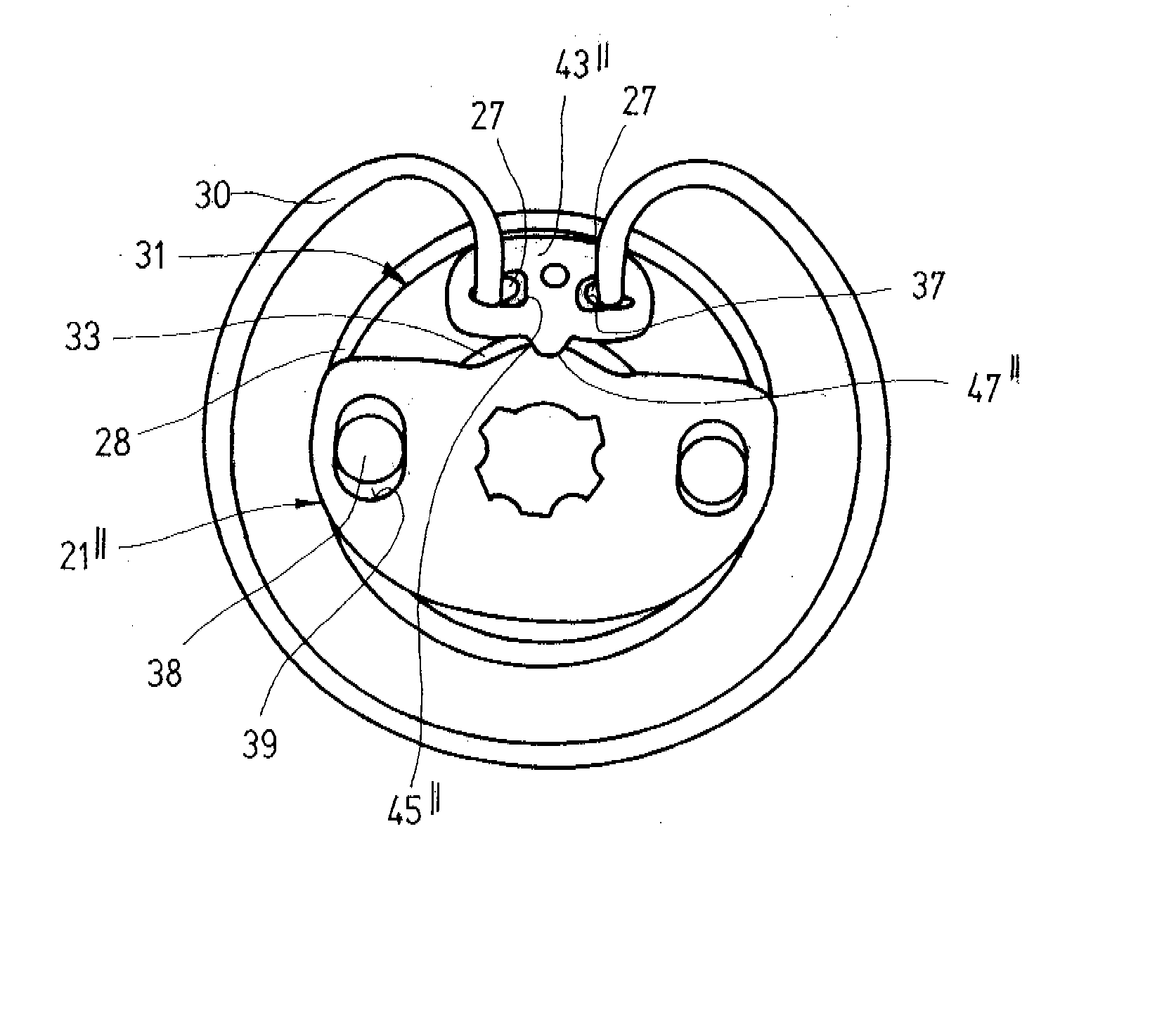
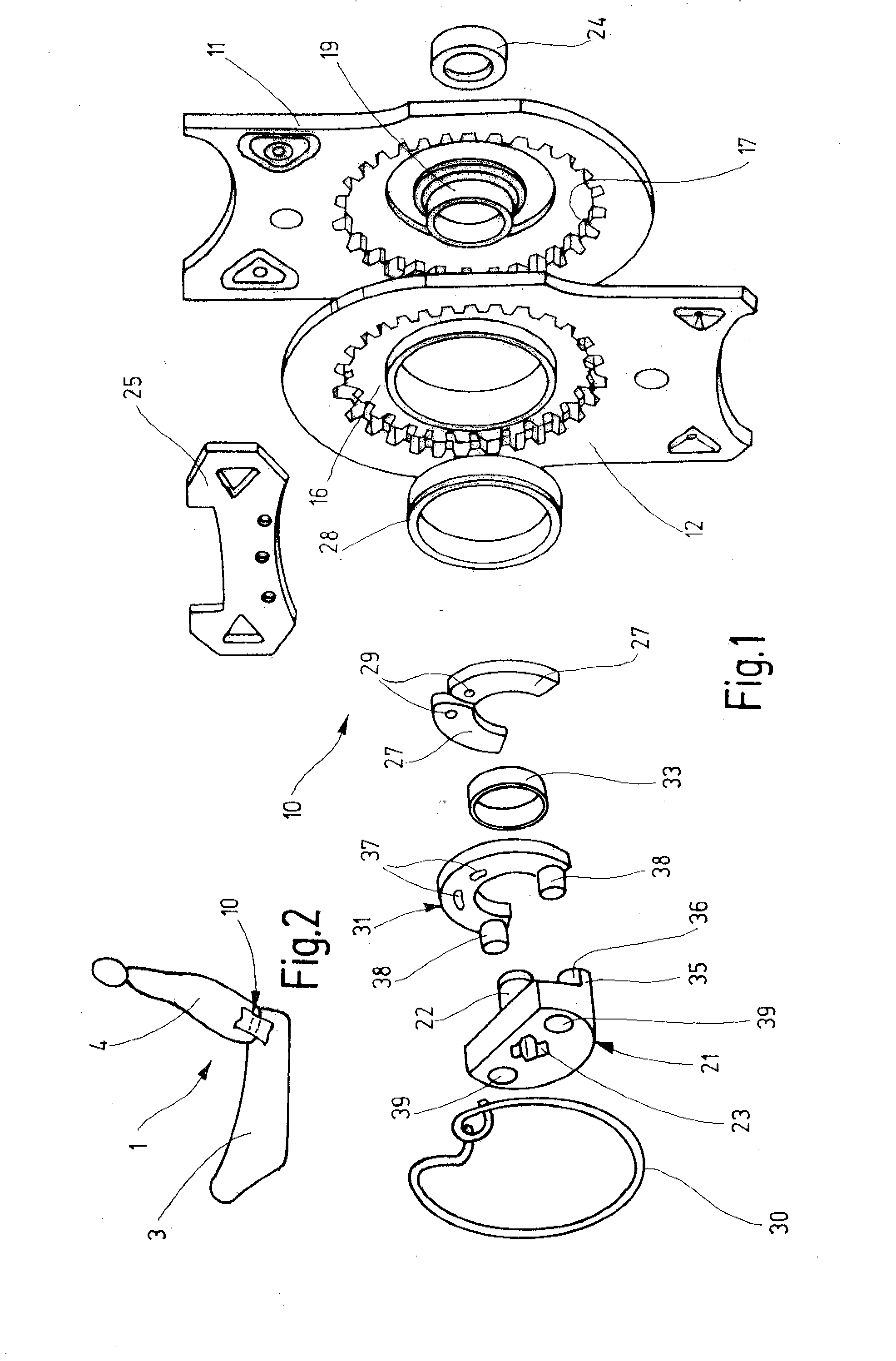
[0025] A vehicle seat 1 for a motor vehicle comprises a seat part 3 and a backrest 4. The inclination of the backrest 4 may be manually adjusted relative to the seat part 3. The inclination adjustment of the backrest 4 is carried out by way of a handwheel provided at the side and a drive shaft that drives two fittings 10 together. The two fittings 10 are respectively attached to the two sides of the vehicle seat 1 and support the backrest 4.

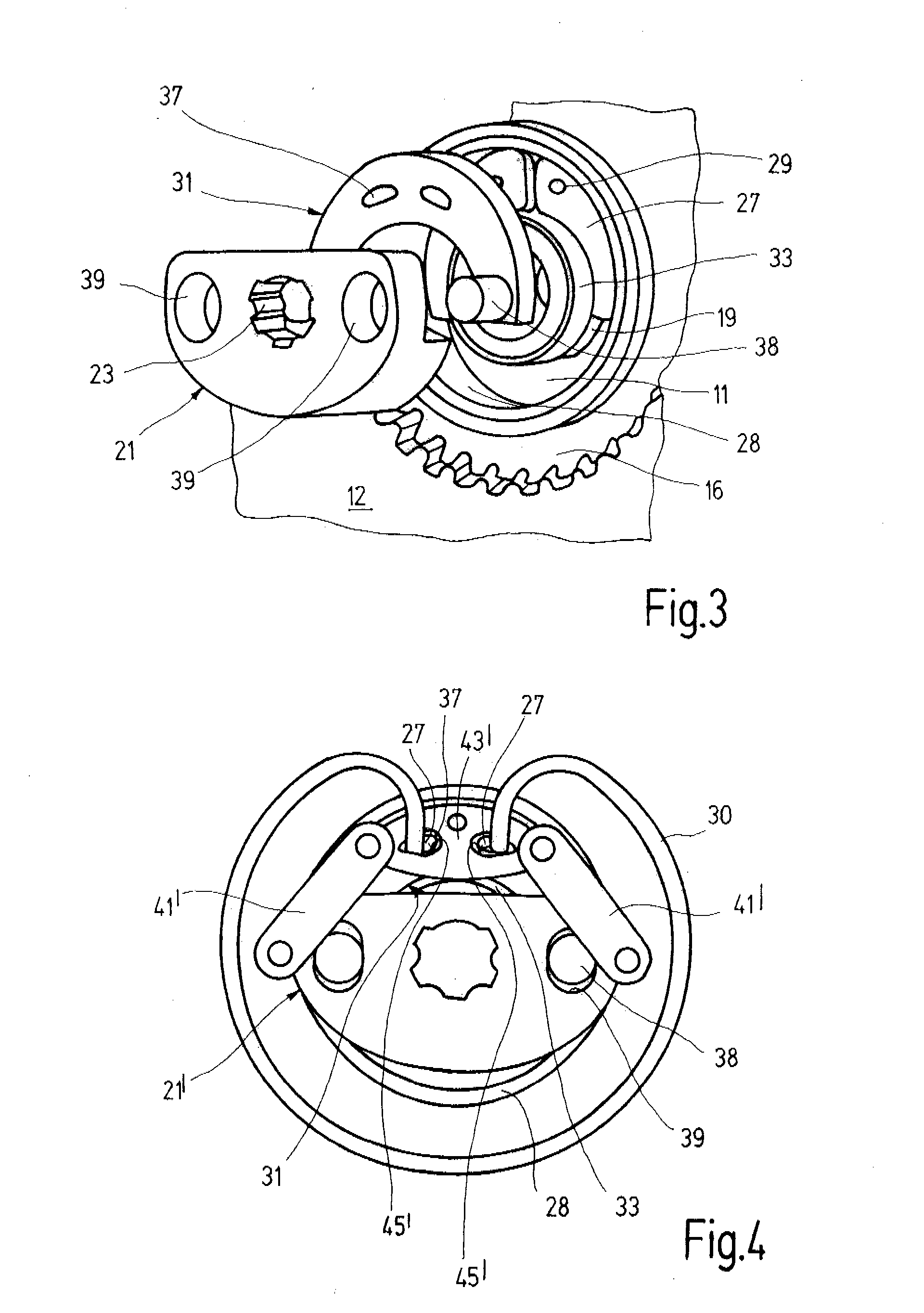
[0026] Each fitting 10 is configured as a geared fitting in which a first fitting part 11 and a second fitting part 12 are connected to one another via a gear for locking and adjusting. The two fitting parts 11 and 12 have a substantially flat shape and are composed of steel. The first fitting part 11 is primarily connected to the structure of the backrest 4 (fixed to the backrest) and therefore shown at the top in the drawings. Accordingly, in the present case, the second fitting part 12 is primarily fixed to the seat part and shown at the bott...


PUM


Abstract

The invention relates to a fitting (10) for the seat of a vehicle, particularly for a motor vehicle, comprising a first fitting part (11), a second fitting part (12) which is mechanically linked to the first fitting part (11), a locking eccentric which is provided primarily to lock the fitting (10), a running eccentric (31) which is primarily provided for driving a relative rolling movement of the second fitting part (12) on the first fitting part (11) in order to adjust the fitting (10), and a driver (21) which controls the locking eccentric at the beginning of the adjusting movement in order to cancel the locking effect and which drives at least the running eccentric (31) during the adjusting movement. The rotating driver (21) impinges upon the rotating running eccentric (31) without any lateral force.

Description

CROSS-REFERENCE TO RELATED APPLICATION [0001] The present application is a continuation of International Application PCT / EP2005 / 013428, which was filed Dec. 14, 2005. The entire disclosure of International Application PCT / EP2005 / 013428, which was filed Dec. 14, 2005, is incorporated herein by reference.BACKGROUND OF THE INVENTION [0002] The present invention relates to a fitting for a vehicle seat, in particular for a motor vehicle seat, with the fitting having a first fitting part, a second fitting part in geared connection with the first fitting part, a locking eccentric, which is provided primarily for locking the fitting, a running eccentric, which is provided primarily for driving a relative rolling movement of the second fitting part on the first fitting part for adjusting the fitting, and a driver that, at the start of the adjusting movement, controls the locking eccentric for canceling the locking effect and during the adjusting movement drives the running eccentric. [0003] ...

Claims


Application Information

Patent Timeline
Patent Type & Authority Applications(United States)
IPC IPC(8): F16C3/00
CPCB60N2/2254B60N2/2252B60N2/20B60N2/22B60N2/225
Inventor VOSS, HEINZEWALD, TOBIASLEHMANN, ULRICHKOMAINDA, ARTURMESSERSCHMIDT, RAINERSCHOLZ, GRITNORBISRATH, ANDREASSTEMMER, JURGEN
Owner KEIPER GMBH & CO KG
Why Eureka
Try Eureka