Device for injecting a mixture of air and fuel, and combustion chamber and turbomachine provided with such a device

Active Publication Date: 2008-01-03
SN DETUDE & DE CONSTR DE MOTEURS DAVIATION S N E C M A
View PDF13 Cites 44 Cited by
  • Summary
  • Abstract
  • Description
  • Claims
  • Application Information

AI Technical Summary

Benefits of technology

[0022]According to a preferred embodiment of the invention, given that the internal radial swirler has a number n of vanes, the sliding bushi

Problems solved by technology

Such an injection device has a relatively large outside diameter, and therefore a relatively large bulk, which is not able to be reduced on account of the presence of certain elements such as the radial swirlers.
If the a

Method used


Image

  • Device for injecting a mixture of air and fuel, and combustion chamber and turbomachine provided with such a device
  • Device for injecting a mixture of air and fuel, and combustion chamber and turbomachine provided with such a device
  • Device for injecting a mixture of air and fuel, and combustion chamber and turbomachine provided with such a device

Examples


Example

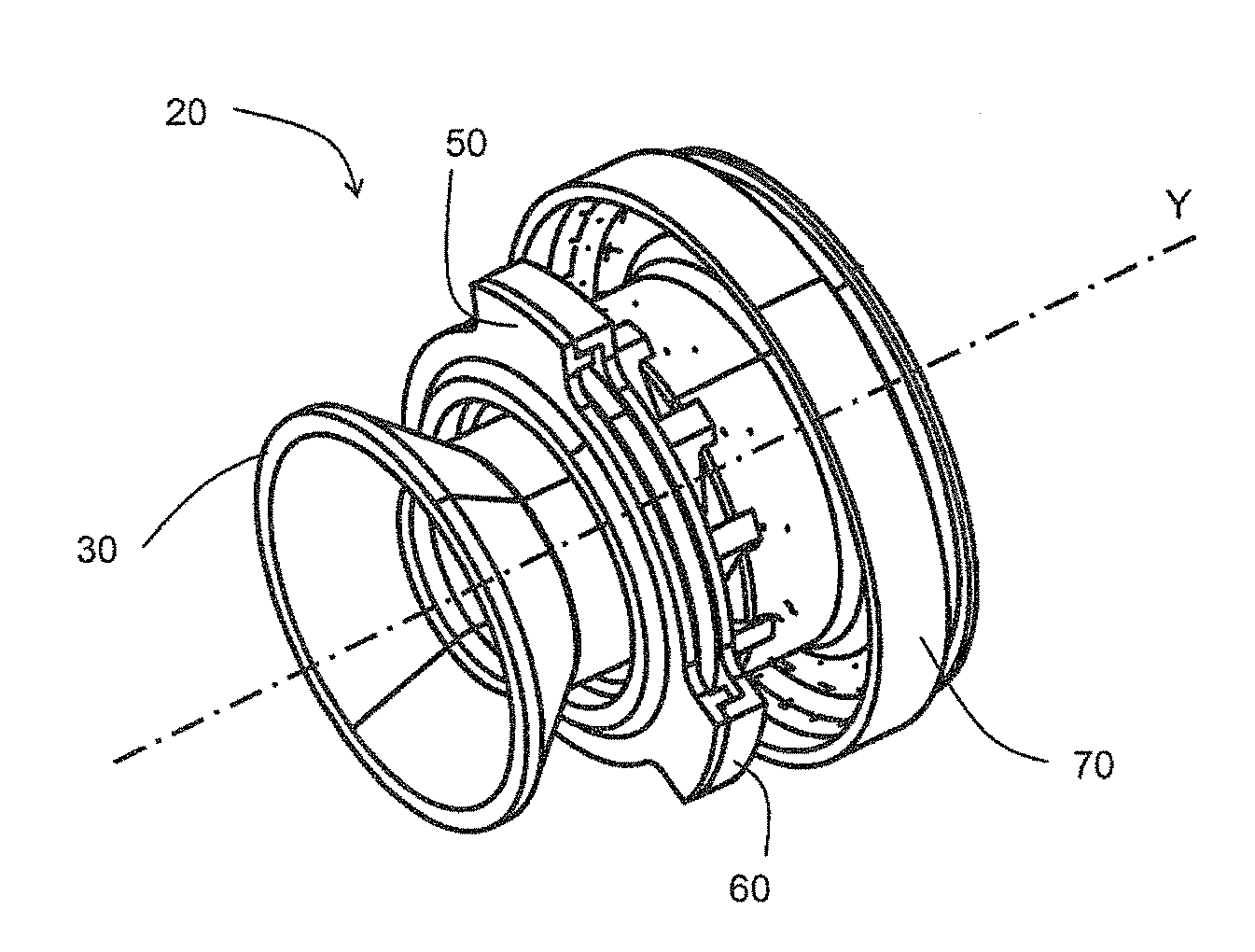
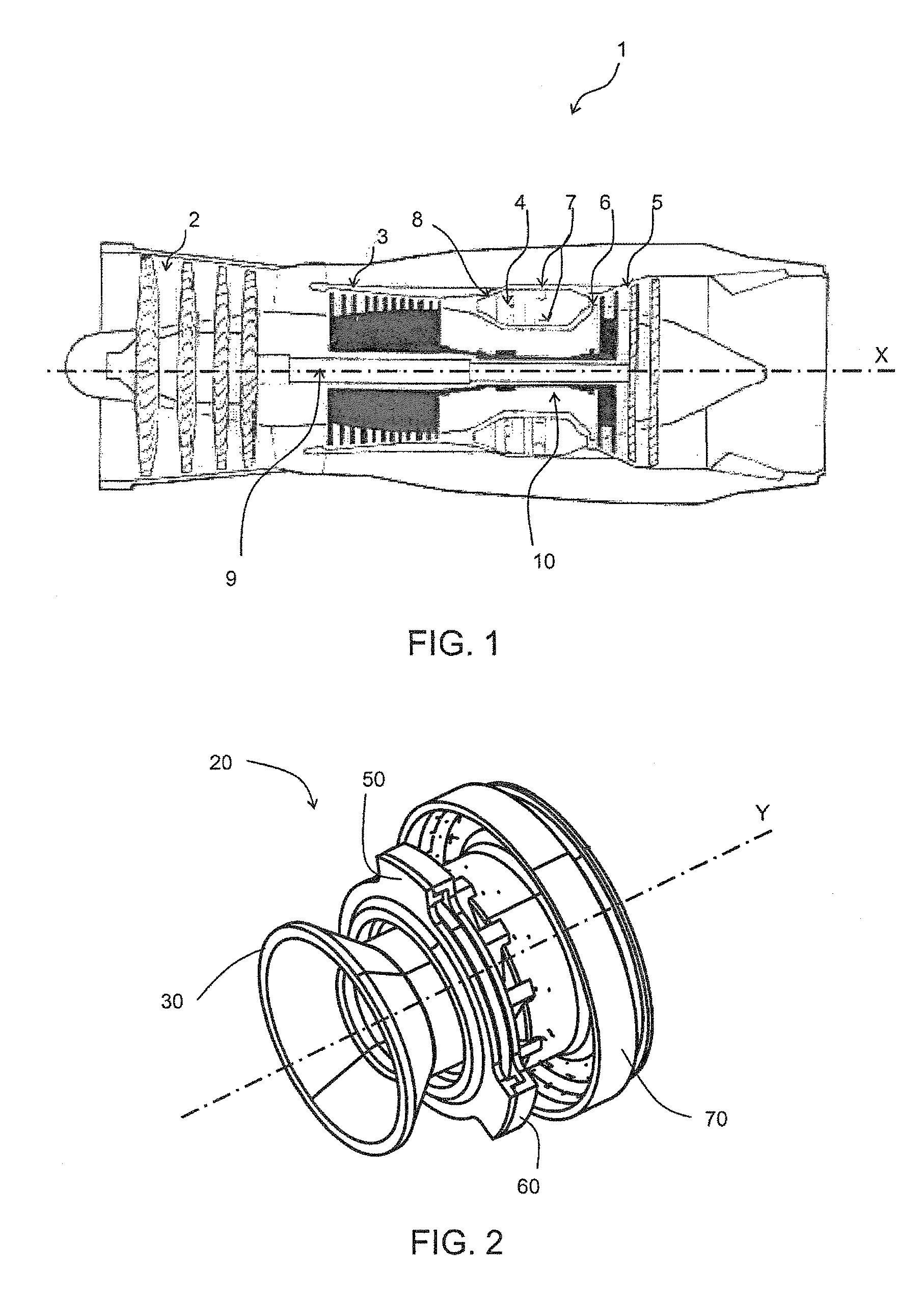
[0040]FIG. 1 shows in section an overall view of a turbomachine 1, for example an aircraft jet engine, comprising a low-pressure compressor 2, a high-pressure compressor 3, a combustion chamber 4, a low-pressure turbine 5 and a high-pressure turbine 6. The combustion chamber 4 may be of the annular type and is defined by two annular walls 7 spaced radially to the axis X of rotation of the jet engine, these walls being connected at their upstream end to an annular chamber end wall 8. The chamber end wall 8 has a plurality of openings (not shown) with a regular circumferential spacing. In each of these openings is mounted an injection device. The combustion gases flow downstream in the combustion chamber 4 and then supply the turbines 5 and 6 which respectively drive the compressors 2 and 3, arranged upstream of the chamber end wall 8, by way of two respective shafts 9 and 10. The high-pressure compressor 3 supplies air to the injection devices and also to two annular spaces respectiv...


PUM


Abstract

The invention relates to a device for injecting an air/fuel mixture into a combustion chamber, which is to be mounted within a restricted space. This injection device (20) comprises a bowl (70) having an external cylindrical wall (73) continued at its downstream end by a divergent section (74) provided, downstream, with a collar (75) having the form of a ring extending radially outward, the divergent section of the bowl being connected, immediately upstream of the flange, by a connecting wall (76) to a cylindrical ring (77), the cylindrical ring and the connecting wall forming a connection rim oriented in the upstream direction. At least one row of vortex holes (79) is formed in the external cylindrical wall, close to its upstream end, and the connecting wall of the connection rim of the bowl is provided with a row of cooling orifices (81) inclined axially at an angle y to the axis of symmetry of the injection device.

Description

BACKGROUND OF THE INVENTION AND DESCRIPTION OF THE PRIOR ART [0001]The invention is concerned with the field of turbomachines and relates to a device for injecting a mixture of air and fuel into a combustion chamber.[0002]It relates more specifically to a novel configuration of an injection device intended to be mounted within a restricted space of a combustion chamber.[0003]Throughout the remainder of the description, the terms “upstream” or “downstream” will be used to denote the positions of the structural elements with respect to one another in the axial direction, taking the gas flow direction as reference. Likewise, the terms “internal” or “radially internal” and “external” or “radially external” will be used to denote the positions of the structural elements with respect to one another in the radial direction, taking the axis of rotation of the turbomachine or the axis of symmetry of the structure in question as reference.[0004]A turbomachine comprises one or more compressor...

Claims


Application Information

Patent Timeline
IPC IPC(8): F23R3/04
CPCF23D11/107F23D14/78F23D2214/00Y02T50/675F23R3/14F23R3/286F23R3/12Y02T50/60
Inventor COMMARET, PATRICE ANDREGUEZENGAR, DOMINIQUEHERNANDEZ, DIDIER HIPPOLYTELUNEL, ROMAIN NICOLASROLLET, PASCALE
Owner SN DETUDE & DE CONSTR DE MOTEURS DAVIATION S N E C M A
Why Eureka
Try Eureka