Electrical Conductor for Transporting Electrical Energy and Corresponding Production Method

a technology of electrical energy transport and electric conductor, which is applied in the direction of insulated conductors, inorganic insulators, cables, etc., can solve the problems of constant increase in electrical power consumption, and achieve the effects of small catenary sag, good mechanical properties, and high electrical properties

Inactive Publication Date: 2013-10-10
LA FARGA LACAMBRA
View PDF16 Cites 26 Cited by
  • Summary
  • Abstract
  • Description
  • Claims
  • Application Information

AI Technical Summary

Benefits of technology

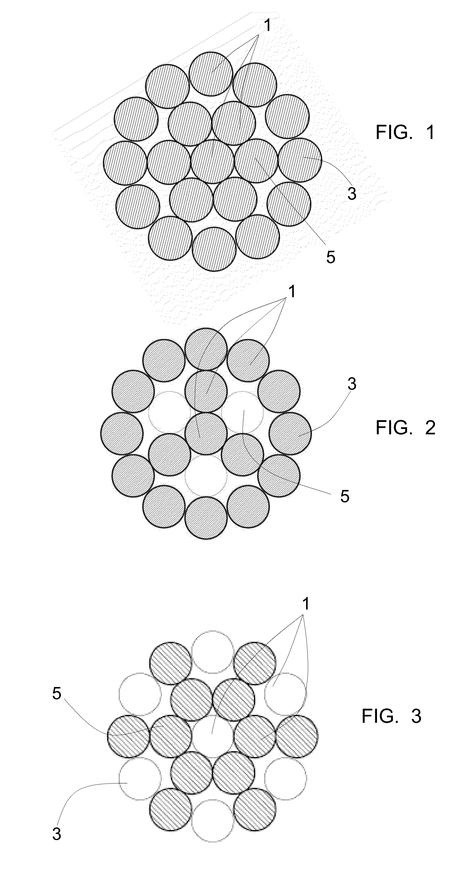
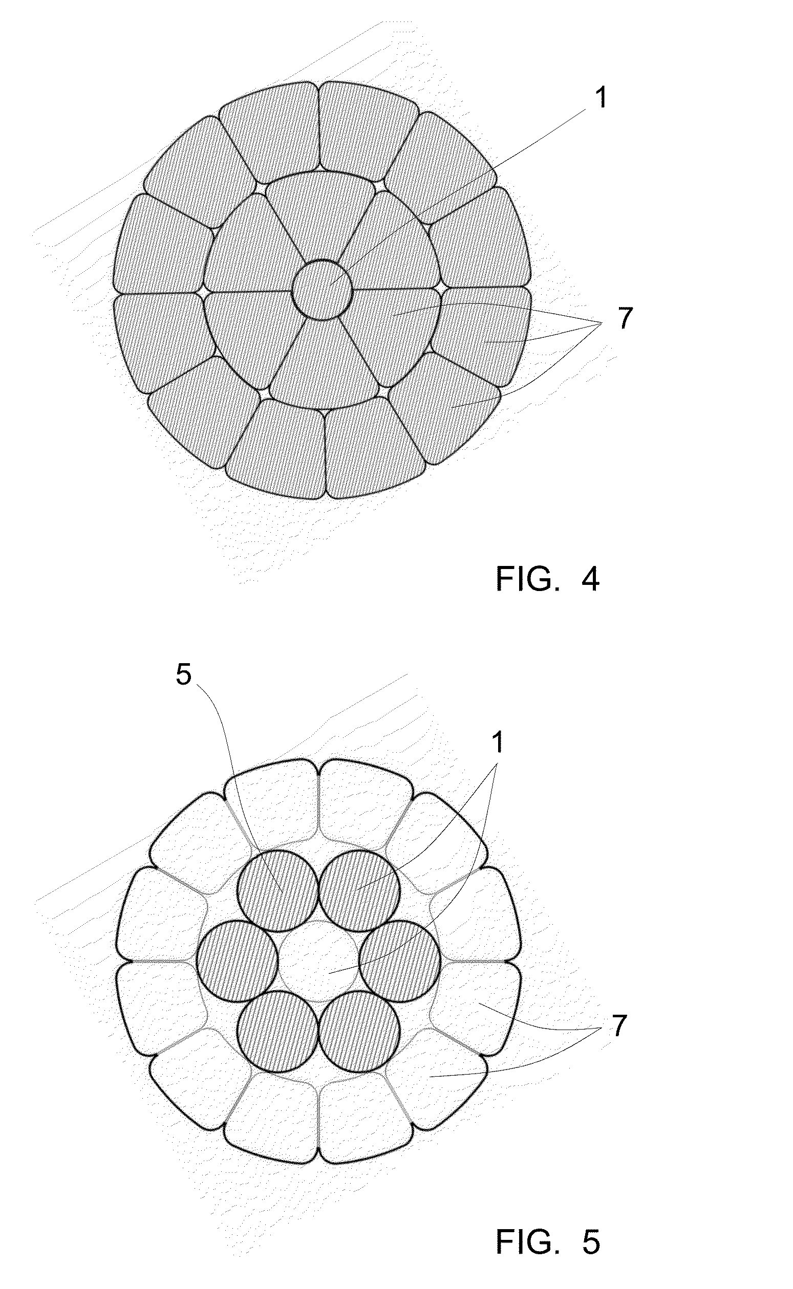
[0027]As will be seen hereinafter, the present invention is appropriate for any type of electrical conductor although the preferred applications are for electrical conductors in which the filamentary members are wires of circular cross section and have a diameter of between 0.3 and 5 mm each, with a total diameter of the cord of between 3.5 and 35 mm. The direction of lay of the electrical conductor can be right, left or in alternating rings. Furthermore, it can have wires of various diameters in the same cord, and even wire combinations with other geometries (wires of trapezoidal, triangular cross section, tubes, etc.). It is also advantageous for the electrical conductor to be a conductor stranded with wires of circular, trapezoidal and / or triangular cross section, without a tubular core, which allows solutions with a smaller catenary sag to be obtained.
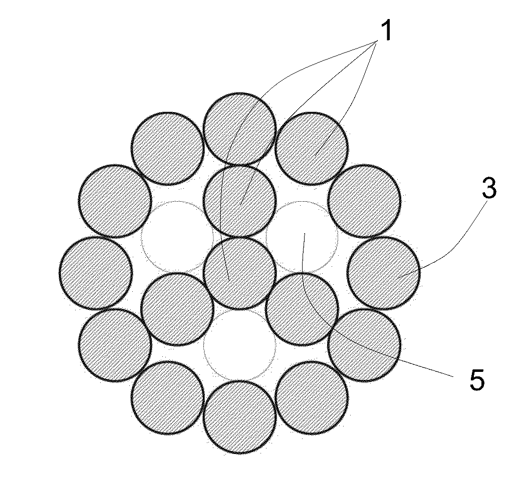
[0028]Preferably the electrical conductor has a plurality of fluorinated polymer coated filamentary members (that is to say with the side surface thereof totally coated with the fluorinated polymer), where said coated filamentary members are distributed in such a way that each of the filamentary members not coated with fluorinated polymer is only in contact with fluorinated polymer coated filamentary members. Indeed, with the non-coated filamentary member being in contact only with coated filamentary members, the non-coated filamentary member is really isolated from the other filamentary members, whereby its behavior relative to the skin effect is as if it were coated.
[0029]Preferably the filamentary member is made from microalloyed copper with an annealing temperature of above 250° C. Indeed, these materials have proved to be particularly appropriate for the transmission of electrical power by overhead lines. They combine high electrical properties with good mechanical properties, a good resistance to wear and a low thermal fluence. Furthermore their high annealing temperature allows the application thereto of fluorinated polymers requiring high curing temperatures.

Problems solved by technology

The consumption of electrical power is constantly increasing.

Method used


Image

  • Electrical Conductor for Transporting Electrical Energy and Corresponding Production Method
  • Electrical Conductor for Transporting Electrical Energy and Corresponding Production Method
  • Electrical Conductor for Transporting Electrical Energy and Corresponding Production Method

Examples


example 1

[0077]A comparative test was carried out between a 95 mm2 microalloyed copper cord with all the wires coated with Xylan 1514® (a polymer composed of polytetrafluoroethylene reinforced with heat resistant resins marketed by Whitford Plastics Ltd. It has a static coefficient of friction of 0.15, and a dynamic coefficient of friction of 0.06), and a cord of the same composition and geometry but without using the coating. The installation was 70 meters in length. When the same voltage was applied to both electrical conductors, the following results were obtained:[0078]with the coated cord, a current intensity of 595 A was reached and a sag of 42 cm[0079]with the uncoated cord, a current intensity of 555 A was reached and a sag of 62 cm[0080]in both cases, the conductor temperature reached 120° C.

[0081]Conclusions: with the electrical conductor formed by coated wires 8% more electrical current is transmitted, and the installation has 48% less sag.

example 2

[0082]A type LA-180 ACSR cable (180 mm2) can work continuously at a maximum temperature of 85° C., which corresponds to a maximum intensity of 425 A. An equivalent conductor thereto, with no need to reinforce the structures, is equivalent to the 95 mm2 microalloyed copper conductor (object of the present invention). This conductor can operate continuously at up to 150° C., and under these conditions, if the wires thereof are coated alternately with fluorinated polymer it can transport an intensity of 700 A. That is to say, 65% more electrical power.

example 3

[0083]Process of application of the fluorinated polymer:[0084]1. Cleaning of the substrate (degreasing)[0085]2. Spraying. It may also be deposited by a dipping or roller impregnation process.[0086]3. If the fluorinated polymer comes in liquid state, it requires drying: 10 min at from 100 to 175° C.[0087]4. Curing: less than 30 minutes at temperatures between 220° C. and 275° C.

[0088]As the curing conditions are at temperatures of above 220° C., if this process is carried out on materials having a lower annealing temperature, their mechanical properties will be affected negatively. Therefore it is particularly advantageous for the conductive material to have an annealing temperature of above the curing temperature. It must be remembered that pure aluminum has an annealing temperature below 120° C., and the annealing temperature of electrolytic copper (ETP) is below 200° C.


PUM

PropertyMeasurementUnit
diameteraaaaaaaaaa
diameteraaaaaaaaaa
temperatureaaaaaaaaaa

Abstract

An electrical conductor for transmission of electrical power, having a total cross-section equal to or above 10 mm2 and comprising a plurality of stranded filamentary members, where at least one of the filamentary members is made from microalloyed copper or microalloyed aluminium having annealing temperatures higher than 250° C., and has the side surface thereof totally coated with a fluorinated polymer. The conductor has a better behavior relative to the skin effect and allows operation at high temperatures. Furthermore, if the electrical conductor is suspended, it has a smaller sag and prevents or reduces the accumulation of ice and/or snow.

Description

FIELD OF THE INVENTION[0001]The invention relates to an electrical conductor for the transmission of electrical power, where the conductor has a total cross-sectional area equal to or over 10 mm2 and comprises a plurality of stranded filamentary members. The filamentary members can be, for example, wires of circular cross-section, wires of trapezoidal cross-section, wires of triangular cross-section, as well as other possible sections.[0002]The invention also relates to a process for manufacturing an electrical conductor according to the invention.[0003]The invention also relates to applications of conductors according to the invention, such as for example overhead power lines and submarine cables that comprise a conductor according to the invention.STATE OF THE ART[0004]In the field of the transmission and distribution of electrical power by means of overhead lines aluminum-steel (ACSR) electrical conductors are well known.[0005]The consumption of electrical power is constantly inc...

Claims


Application Information

Patent Timeline
Patent Type & Authority Applications(United States)
IPC IPC(8): H01B7/30H01B7/14H01B3/02
CPCH01B3/445H01B7/303H01B3/025H01B7/14H01B7/30D07B1/147D07B2205/2071H01B5/08H01B1/026C22C9/00C22C9/02C22C21/00C22C21/08C22F1/04C22F1/05C22F1/08H01B1/023D07B2801/18
Inventor FONTANA, LLUIS RIERACRUSELLAS, NURIA FERRERZAMORA, MIQUEL GARCIAARDERIU, ORIOL GUIXAMARSA, CRISTINA GARCIAALVAREZ, FERRAN ESPIELL
Owner LA FARGA LACAMBRA
Why Eureka
Try Eureka