Apparatus and method for lighting a collapsible structure

a technology of collapsible structures and apparatuses, applied in the field of collapsible structures, can solve the problem that many conventional batteries supply only a limited amount of electric power, and achieve the effect of reducing the number of conventional batteries and reducing the amount of electricity

Inactive Publication Date: 2008-01-03
NORTHPOLE
View PDF14 Cites 21 Cited by
  • Summary
  • Abstract
  • Description
  • Claims
  • Application Information

AI Technical Summary

Benefits of technology

[0006] In another aspect, a method for lighting an interior space defined by a collapsible structure is provided. The method includes constructing a collapsible structure including a hub and a plurality of frame members each pivotally coupled to the hub. The plurality of frame members at least partially form a collapsible frame assembly of the collapsible structure. A solar apparatus is removably coupled to the hub. The solar apparatus includes a solar panel configured to absorb solar energy from the sun and a power source operatively coupled to the solar panel and configured to convert the solar energy to electrical energy. A load device is removably coupled to the hub and electrically coupled to the solar apparatus.
[0004] In one aspect, a solar power generator is provided. The solar power generator includes a hub defining a passage. A solar apparatus is removably coupled to the hub. The solar apparatus includes a solar panel configured to absorb solar energy from the sun and a power source configured to convert the solar energy absorbed by the solar panel to electrical energy. A load device is removably coupled to the hub. The load device includes a sleeve positioned within the passage and operatively coupling the load device to the power source. The power source is configured to supply electrical energy to the load device.
[0014]FIG. 8 is an exploded view an exemplary solar power generator with a light source in a collapsed configuration;

Problems solved by technology

However, many conventional batteries supply only a limited amount of electric power.

Method used


Image

  • Apparatus and method for lighting a collapsible structure
  • Apparatus and method for lighting a collapsible structure
  • Apparatus and method for lighting a collapsible structure

Examples


Embodiment Construction

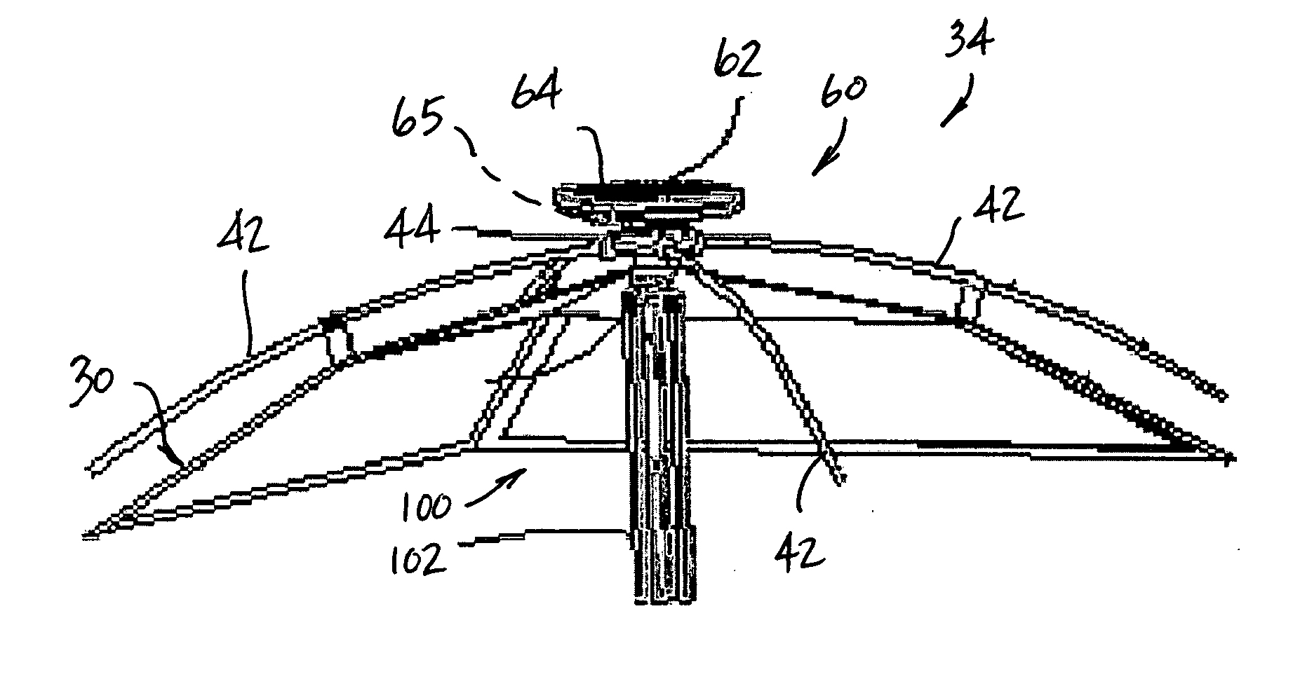
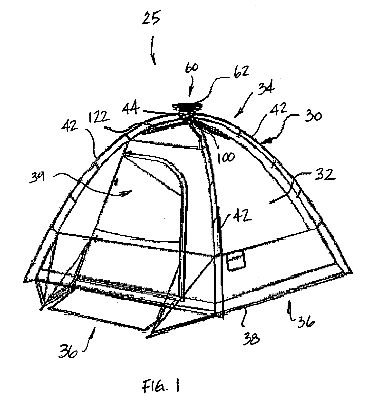
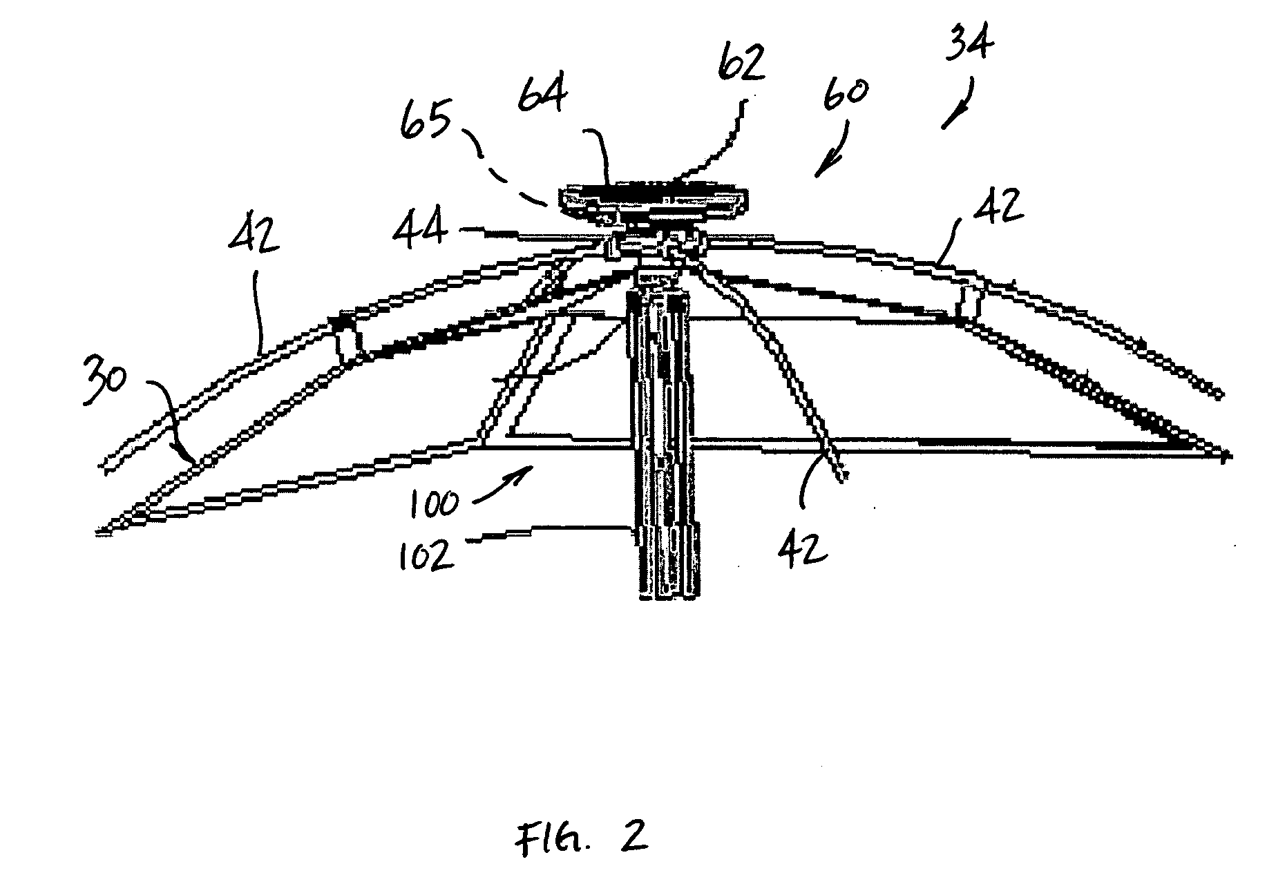
[0024] The present invention provides a collapsible structure, such as a tent, a canopy or a gazebo, including an apparatus for facilitating converting solar energy to electrical energy for supplying electric power to a load device, such as an appliance and / or a lighting device for lighting an interior space defined by the collapsible structure and / or an exterior area about the collapsible structure. In one embodiment, the apparatus utilizes photovoltaic principles to generate electrical energy from solar power obtained from the sun.

[0025] The present invention is described below in reference to its application in connection with and operation of an apparatus and method for facilitating lighting an interior space defined by a collapsible structure, such as a tent, a canopy or a gazebo. However, it will be apparent to those skilled in the art and guided by the teachings herein provided that the invention is likewise applicable to any suitable collapsible and / or permanent structure f...


PUM


Abstract

A solar power generator includes a hub defining a passage. A solar apparatus is removably coupled to the hub. The solar apparatus includes a solar panel configured to absorb solar energy from the sun and a power source configured to convert the solar energy absorbed by the solar panel to electrical energy. A load device is removably coupled to the hub. The load device includes a sleeve positioned within the passage and operatively coupling the load device to the power source. The power source is configured to supply electrical energy to the load device.

Description

CROSS REFERENCE TO RELATED APPLICATIONS [0001] This application claims the benefit of Chinese Patent Application 200620082552.2 entitled “Solar Normal Tent” filed on Mar. 30, 2006, which is hereby incorporated by reference in its entirety. BACKGROUND OF THE INVENTION [0002] This invention relates generally to collapsible structures, such as tents and gazebos, and, more particularly, to collapsible structures having an apparatus for converting solar energy to electrical energy and providing that energy to an interior space defined by the collapsible structure. [0003] Camping and social activities are becoming increasingly popular. With people's current living standards improving, so are the demands for simplified and user-friendly camping and / or social activity structures. For example, tents are becoming a favored necessity for camping activities. To provide more enjoyment for the camper, electric home appliances and / or lighting devices provide the modern conveniences that the camper...

Claims


Application Information

Patent Timeline
Patent Type & Authority Applications(United States)
IPC IPC(8): H01L31/045H01L31/042H02S30/20
CPCE04H15/10Y02B10/14H02S20/23Y02B10/12H02S20/00Y02E10/50H02S10/40H02S40/38Y02B10/10Y02E70/30
Inventor YUL, LEE PILJIU, HUANG CHANG
Owner NORTHPOLE
Why Eureka
Try Eureka