Wind & solar powered heat trace with homeostatic control

a technology of solar energy and heat trace, which is applied in the directions of emergency power supply arrangement, safety/protection circuit, transportation and packaging, etc., to achieve the effect of preventing them from freezing, and maximizing the use of stored energy

Inactive Publication Date: 2012-05-10
CULVER INDS
View PDF99 Cites 28 Cited by
  • Summary
  • Abstract
  • Description
  • Claims
  • Application Information

AI Technical Summary

Benefits of technology

[0015]The present invention provides a homeostatic HTS that includes a plurality of heat trace sections powered by wind and solar electrical generators wherein the solar power may be used to backup the electrical system when wind velocities are too low or high. Energy from the generators is stored in a bank of batteries and then converted into AC power by a DC to AC inverter. The AC power is distributed to the heat trace sections by the invention's novel control system, which is programmed in a programmable logic controller (PLC). The homeostatic variable being regulated is the voltage of the batteries, which is maintained near its maximum charge, the receptors that monitor environmental changes are thermocouple sensors, the stimulus monitored is temperature, the control center is the invention's control system in the PCL, and the effectors receiving information from the PCL are relays which distribute the AC power to the heat trace sections, thereby maximizing the use of stored energy for heating vulnerable components and preventing them from freezing.
[0016]The system's novel control system distributes power to heat trace sections requiring power to prevent freezing. When wind power is sufficient, homeostasis is maintained by energy from the aerogenerator. When wind power is restricted (high or low wind velocity) and solar power is sufficient to fully backup the system, homeostasis is maintained by energy from both generators. If wind power is restricted further or solar power is insufficient to fully back up the system, the system may ration energy to heat trace sections as needed to prevent freezing. Thus, when both wind and solar power are restricted and homeostasis cannot be maintained, the PLC alternates power distribution to each heat trace section, thereby maximizing the use of stored energy to prevent freezing. In the event the batteries become depleted, the PLC activates an alert system.
[0017]The present invention may be used to prevent freezing of any type of equipment in remote locations, and is particularly adapted to keep vulnerable components and pipes at remote oil and gas wells from freezing. In that setting, the invention systematically allocates heat according to real time needs of vulnerable components of one or more remote oil and gas wells and mitigates nearly all of the problems with remote electrical heat trace systems in a cost-effective and environmentally friendly HTS that can be easily set up at well heads serviced by it.

Problems solved by technology

If wind power is restricted further or solar power is insufficient to fully back up the system, the system may ration energy to heat trace sections as needed to prevent freezing.

Method used


Image

  • Wind & solar powered heat trace with homeostatic control
  • Wind & solar powered heat trace with homeostatic control
  • Wind & solar powered heat trace with homeostatic control

Examples


Embodiment Construction

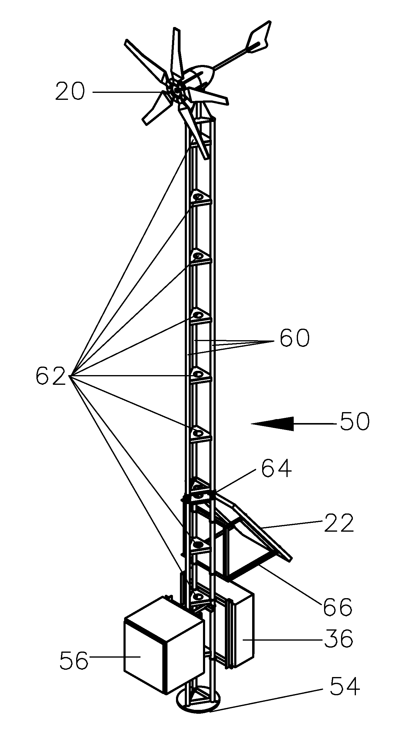
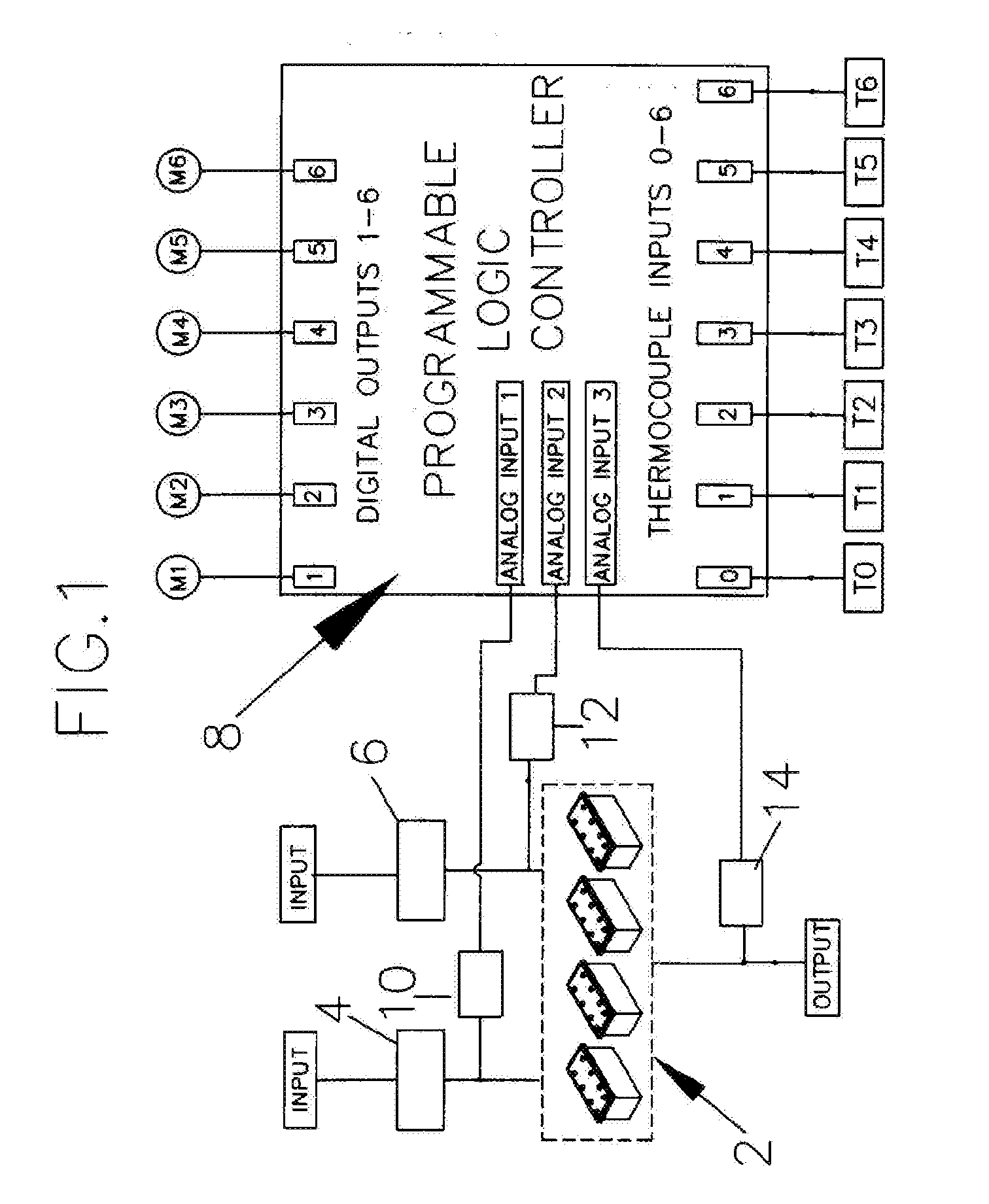
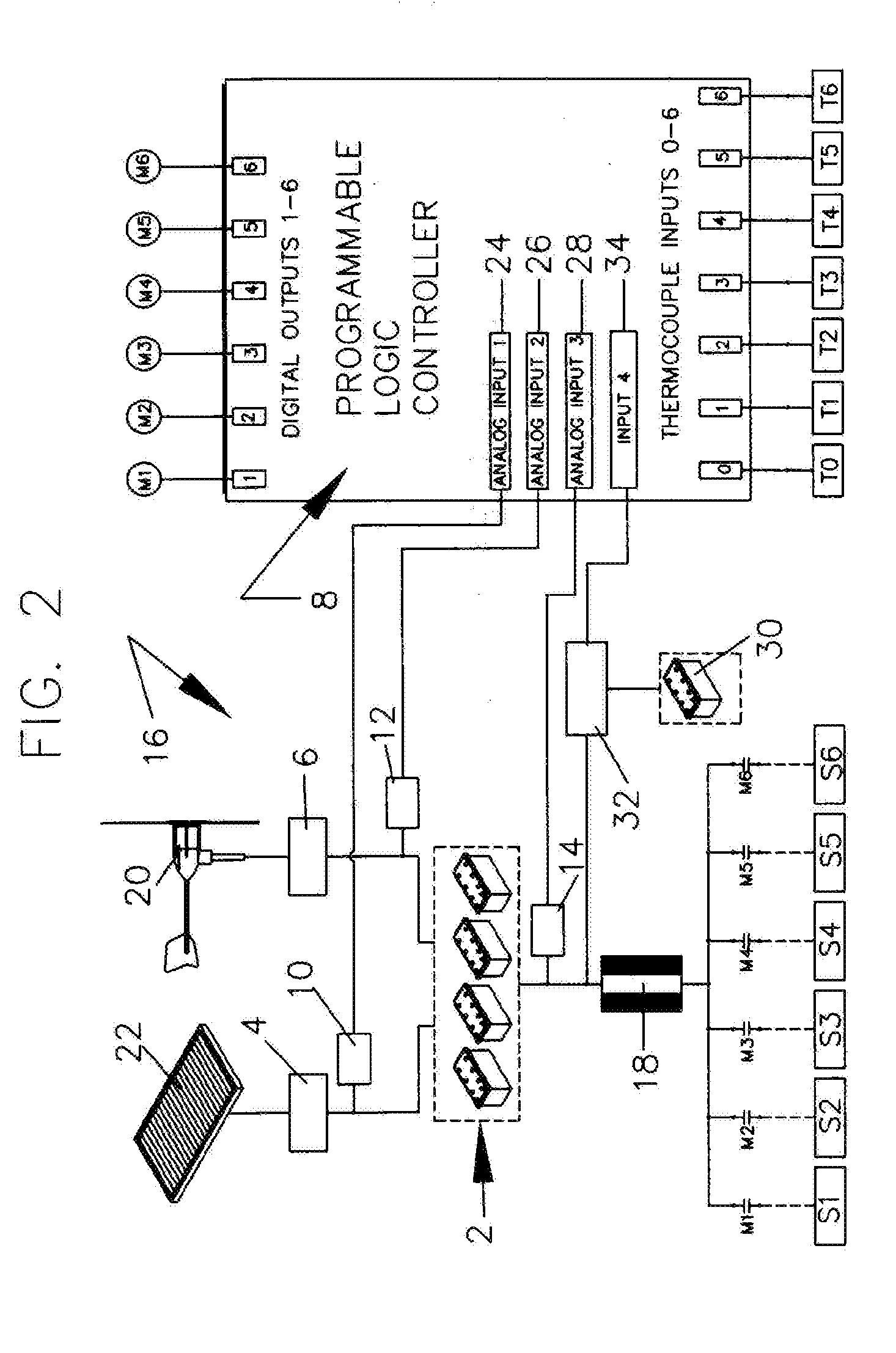
[0032]The present invention comprises one or more sources of energy input (E(in)) through a novel homeostatic control system with output (E(out)) to one or more energy-consuming components. In the HTS, E(in) is generated from wind and sunlight by an aerogenerator and at least one solar panel and stored in a bank of deep-cell batteries, and may be consumed by at least one heat trace section used to prevent equipment from freezing. The control system maintains homeostasis when E(in)=E(out), and the batteries in the bank are fully charged.

[0033]As in all homeostatic control systems, the control system for the present invention has a variable (V) being controlled, and at least three independent components for regulating it. The receptor, R monitors environmental changes and sends information about the environment to a control center, C. C sets the range homeostasis and sends information to an effector, F. If V moves out of its homeostatic range, F attempts to implement a correction to r...


PUM


Abstract

A homeostatic heat trace powered by wind and solar electrical generators for preventing freeze-up of equipment at remote sites. A heat trace system wherein solar power may be used as backup when wind velocities are too low or high. A heat trace with a UPS backup for preventing freeze-up of equipment at remote sites during power failure. A homeostatic control system for maximizing the utilization of energy stored in a bank of batteries. A programmable logic controller with a homeostatic control system for maintaining battery charge. A homeostatic heat trace system powered by wind and backed up by solar power to prevent freeze-up of equipment at remote sites, including oil and gas wells.

Description

BACKGROUND OF THE INVENTION[0001]A heat trace system (HTS) is basically a device that distributes alternating current (AC) electricity to one or more heat trace sections where heating elements maintain or raise the temperature of equipment (e.g. insulated pipes, vessels, etc.).[0002]Heating prevents equipment from freezing by replacing heat lost to the atmosphere. If the heat replaced matches the heat lost due to falling ambient temperatures, the equipment temperature remains constant. An ambient temperature thermocouple sensor together with heat trace thermocouple sensors may be used to control equipment temperature by activating their heat trace sections before the equipment freezes. 40° F. is the usual standard for turning on heat.[0003]Since heat trace systems require alternating current, they are well adapted for use near commercial AC power outlets. However there is also a need for heat trace systems at remote locations where there is no commercial source of AC. The present in...

Claims


Application Information

Patent Timeline
Patent Type & Authority Applications(United States)
IPC IPC(8): H02J9/00
CPCH02J7/0029H02J7/0047H02J7/34Y02B10/72H02J9/06H02J2007/0037H02J2007/0049H02J7/35H02J7/00302H02J7/0049Y02B10/70H02J7/0048
Inventor CULVER, BRANDON
Owner CULVER INDS
Why Eureka
Try Eureka