Solar Power Generator

a solar power generator and solar energy technology, applied in the field of solar energy, can solve the problems of increased efficiency, increased cost, and limited penetration to very few commercial applications, and achieve the effects of reducing the requirement for tracking systems, improving performance, and increasing the effective number of suns

Inactive Publication Date: 2011-08-11
TAN RAYMOND
View PDF16 Cites 29 Cited by
  • Summary
  • Abstract
  • Description
  • Claims
  • Application Information

AI Technical Summary

Benefits of technology

[0030]As such the majority of the prior art in CPV / CST systems have addressed either concentrator designs, for example to increase effective number of suns or reduce requirements for tracking systems, or thermal management systems. Such systems within the prior art being targeted primarily to flat PV panel geometries with low concentration factor concentrators to improve performance without increased cost and complexity from tracking systems, or high concentration systems with special PV cells capable of operating at elevated temperatures or CST systems that generate electricity as a secondary step after the initial heating of a gas or liquid at the concentration point of the CST optical assembly.
[0031]As such it would be beneficial for PV systems in residential, commercial, and industrial environments to exploit solar concentrators to increase the electricity output per unit area of deployed solar cell. It would be further beneficial for such PV systems to employ low cost tracking systems to further enhance overall electrical output and be absent complex or expensive active thermal management aspects which increase cost and reduce reliability.

Problems solved by technology

At present renewable energy sources account for approximately 1% of global energy production and penetration has been limited to very few commercial applications.
However, their increased efficiency comes at a cost as their manufacturing processes are more expensive and largest commercial wafers being 100 mm (4 inch) whereas silicon commercial wafers are typically 200 mm (8 inch) and 300 mm (10 inch) today.
A dominant raw material cost being the silicon wafers upon which the PV cells are fabricated.
However, it would be apparent that increasing the area of the PV cells whilst increasing the electrical power of the solar assembly does so with a cost that is approximately linear to the output, as this is essentially linear with area of the PV cells, silicon used, packaging materials, assembly etc.
However, challenges for these CPV approaches include additional complexity, a much smaller market presence, and a very limited history of reliability / field-test data.
However, to date, the total installed CPV capacity is <1 MW in the United States and only a few MW worldwide, virtually all using silicon PV cells.
Thus, the fundamental challenge of CPV is to lower cost, increase efficiency, and demonstrate reliability to overcome the barriers to entry into the market at a large scale.
However CPV systems typically position the PV cell at the focal point of the optical train such that the increased complexity of two axis or altitude-azimuth tracking is required.
Medium concentration systems (MCPV), 100-300 suns, require solar tracking and associated control plus require cooling and hence complexity.
The design increases solar PV system costs by requiring that the PV cells be mounted and interconnected in optically transparent assemblies and thermal management of the PV cells.

Method used


Image

  • Solar Power Generator
  • Solar Power Generator
  • Solar Power Generator

Examples


Embodiment Construction

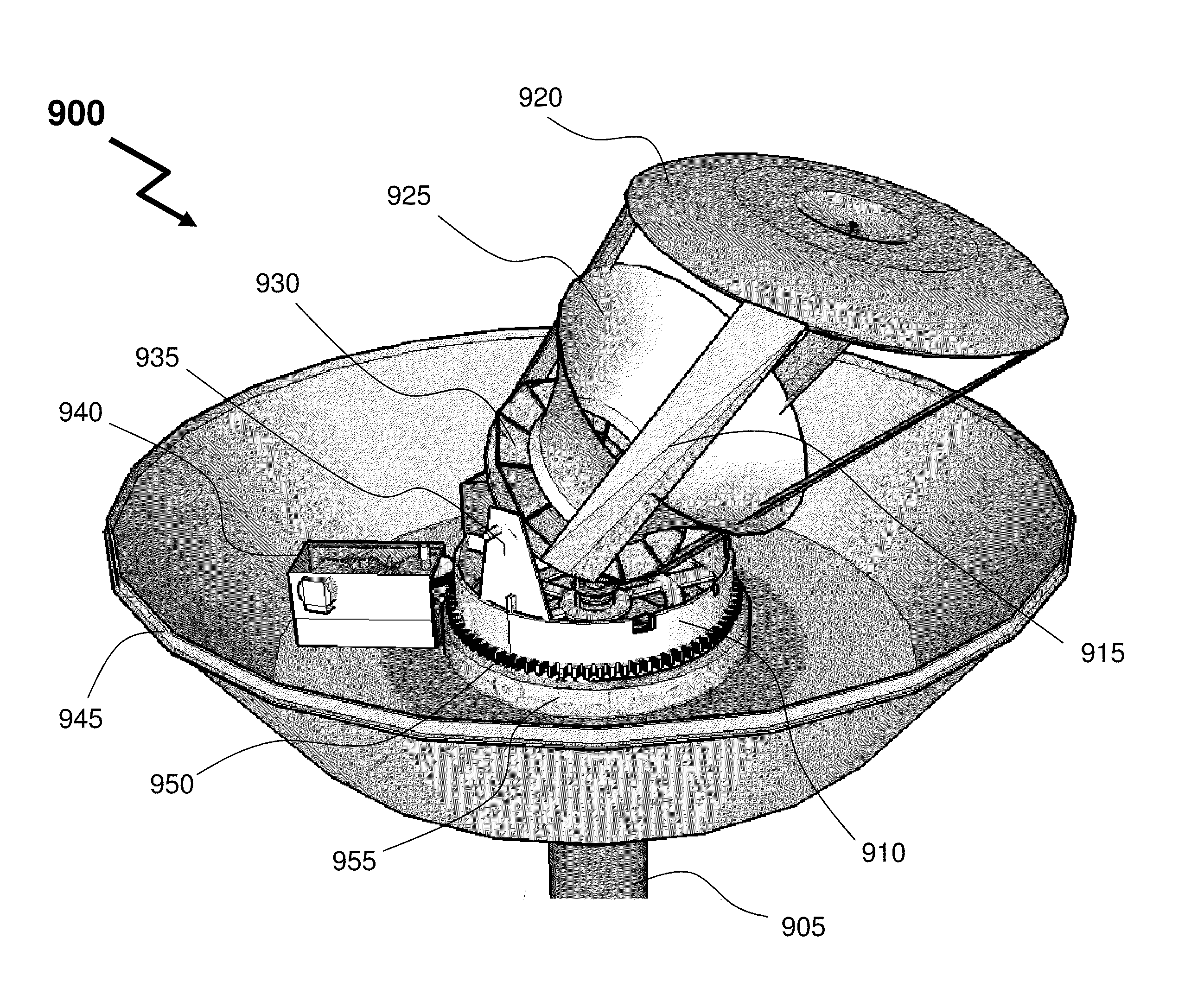
[0062]The present invention is directed to providing a compact solar power concentrator with chronological tracking without requiring active thermal management.

[0063]Reference may be made below to specific elements, numbered in accordance with the attached figures. The discussion below should be taken to be exemplary in nature, and not as limiting of the scope of the present invention. The scope of the present invention is defined in the claims, and should not be considered as limited by the implementation details described below, which as one skilled in the art will appreciate, can be modified by replacing elements with equivalent functional elements.

[0064]Illustrated in FIG. 7 is a solar power generator 700 according to an embodiment of the invention. As shown solar power generator 700 comprises a mounting post 710, lower external body 720, upper external body 730, and lid 740. Upper external body 730 and lid 740 are transparent to at least significant portion of the wavelength sp...


PUM


Abstract

Renewable energy sources provide electricity without consuming fossil fuels and contributing to emissions that impact the global environment. Unlike wind and water methods solar photovoltaic generators provide this renewable energy without geographic or meteorological limitations. However, today electricity generation from solar using photovoltaics is more expensive than fossil fuel sources and is generally limited to deployments with large planar photovoltaic panels. According to embodiments of the invention concentrator based azimuth-altitude tracking solar power generators are provided offering reduced electricity generation costs, reduced installation costs, increased flexibility in deployment and locations of deployment, and initial system costs. The optical assembly comprises a concentrating lens and a reflector to couple the solar radiation to the photovoltaic cell. The concentrating lens is offset out of the plane parallel to the photovoltaic cell whilst the reflector and the reflector may be disposed angularly offset to an axis perpendicular to the photovoltaic cell.

Description

FIELD OF THE INVENTION[0001]This invention relates to solar energy and more specifically to an optical configuration for increasing output power.BACKGROUND OF THE INVENTION[0002]Interest in photovoltaic cells has grown rapidly in the past few decades, such photovoltaic cells comprising semiconductor junctions such as p-n junctions. It is well known that light with photon energy greater than the band gap of an absorbing semiconductor layer in a semiconductor junction is absorbed by the layer. Such absorption causes optical excitation and the release of free electrons and free holes in the semiconductor. Because of the potential difference that exists at a semiconductor junction (e.g., a p-n junction), these released holes and electrons move across the junction in opposite directions and thereby give rise to flow of an electric current that is capable of delivering power to an external circuit. As such photovoltaic cells offer a source of renewable energy as once installed all they re...

Claims


Application Information

Patent Timeline
Patent Type & Authority Applications(United States)
IPC IPC(8): H01L31/00F24S23/30F24S23/70
CPCF24J2/085F24J2/10F24J2/4609F24J2/4621F24J2/5417H01L31/0547Y02E10/52Y02E10/43Y02E10/47H01L31/0543G02B3/08F24S40/10F24S40/50F24S23/70F24S30/45F24S23/31
Inventor TAN, RAYMOND
Owner TAN RAYMOND
Why Eureka
Try Eureka