
LED flasher

Active Publication Date: 2008-01-03
ADB SAFEGATE AMERICAS LLC
View PDF9 Cites 19 Cited by
  • Summary
  • Abstract
  • Description
  • Claims
  • Application Information

AI Technical Summary

Benefits of technology

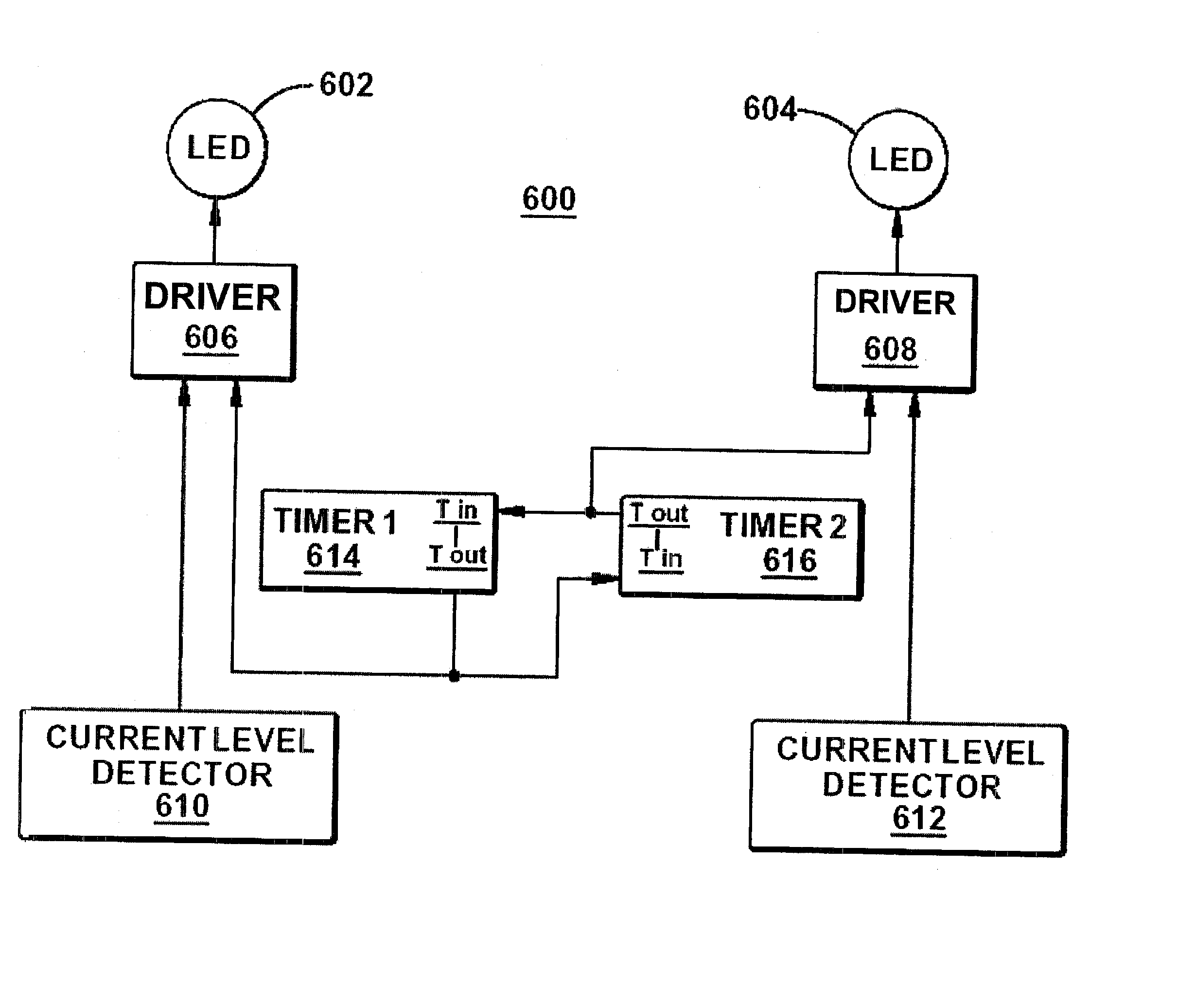
[0007] In accordance with an example embodiment, there is disclosed herein a lighting system for producing a flash at a predetermined effective intensity. The lighting system comprising a light emitting device, a driver circuit coupled to the light emitting device operable to operate the light emitting device at a predetermined current to produce a flash at a desired intensity, and an

Problems solved by technology

Xenon flash lamp systems have some drawbacks that LED (Light Emitting Diode) lamps do not have.
Xenon lamps require extremely high voltages (as high as 15 KV), requiring expensive power supplies along with safety issues and reliability problems associated high voltages.
For dimming purposes, the light output for xenon flash lamps are adjusted by switching in and out large amounts of capacitance, requiring additional complexity in the control circuit that impacts cost and reliability.
However, a problem with prior art LED systems is that they do not provide the same intensity as a xenon flash tube.

Method used


Image

  • LED flasher
  • LED flasher
  • LED flasher

Examples


Embodiment Construction

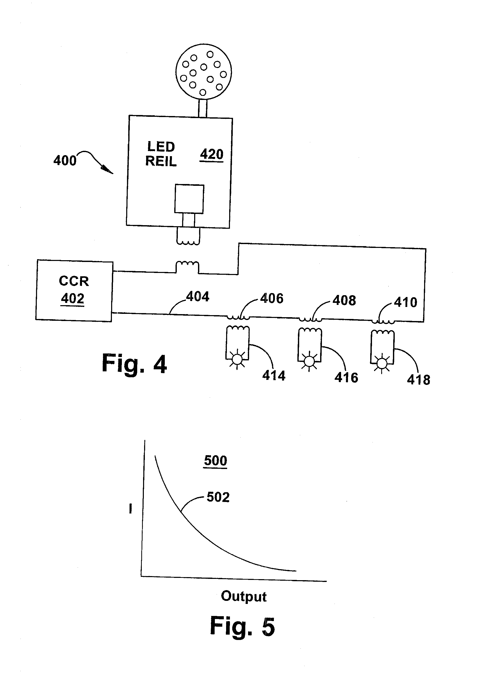
[0033] Throughout this description, the preferred embodiment and examples shown should be considered as exemplars, rather than limitations, of the present invention. An aspect of the present invention is to utilize Light Emitting Diodes (LEDs) for flashing light systems. In accordance with an aspect of the present invention, the LED flashing light systems can meet FAA (Federal Aviation Administration) and ICAO (International Civil Aviation Organization) photometric specifications for flashing light systems, such as Runway Edge Identifier (REIL) and Medium Intensity Approach Lighting Sequence Flasher (MALSR) or high intensity Approach Lighting Sequenced Flasher (ALSF).

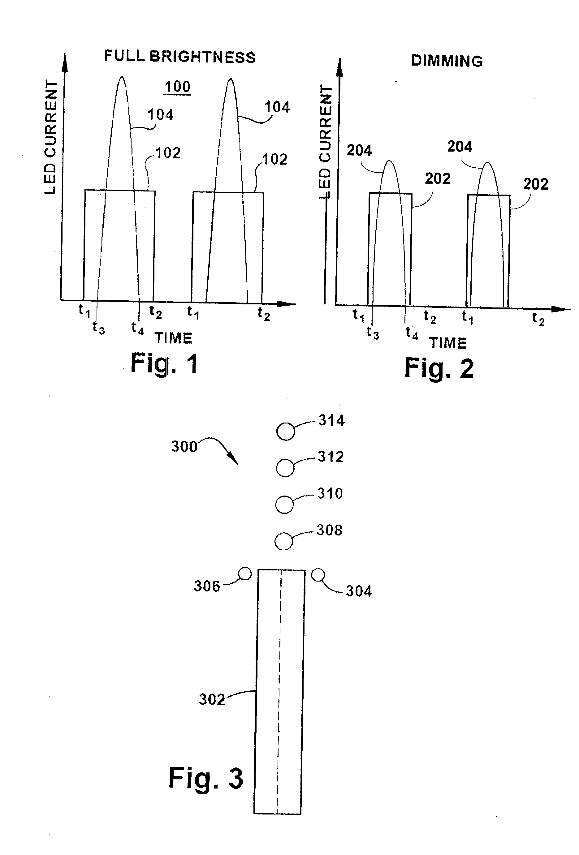
[0034] An aspect of the present invention relies on two characteristics of the human visual system involved in the application of LEDs to airport flash devices, which are as follows. The first concerns the perceived flash duration. For flashes shorter than about 70-100 ms the eye cannot accurately judge the flash durat...


PUM


Abstract

A system and method for producing a flash of a desired intensity and duration utilizing devices of a lower intensity, such as light emitting diodes (LED's). The on period of the LED is lengthened so that the product of the LED's intensity and the on period is approximately equal to the product of the desired intensity and duration of the flash. A parameter for determining intensity, such as operating current or voltage, can be measured and the on period can be adjusted accordingly. The device can be turned on responsive to an external trigger signal, and a timer can be utilized to turn the device on if the external trigger signal is not received within a predetermined time.

Description

CROSS-REFERENCE TO RELATED APPLICATIONS [0001] This application claims the benefit of priority of U.S. Provisional Application No. 60 / 746,218 filed May 2, 2006.BACKGROUND OF THE INVENTION [0002] The present invention relates generally to flash lamp systems such as are often used in airfield lighting systems. [0003] In current airport approach systems, xenon flash lamps are used to produce high intensity white flashing light. These lights may be flashed in two modes, the first being in unison on either side of the runway threshold, which are known as Runway Edge Identifier Light (REL). The second mode is in sequence pulsing towards the runway known as Medium Intensity Approach Lighting Sequenced Flasher (MALSR) or Approach Lighting Sequenced Flashers (ALSF). [0004] Xenon flash lamps produce very brief pulses of high intensity light that are measured in the microsecond range up to a few milliseconds. Xenon flash lamp systems have some drawbacks that LED (Light Emitting Diode) lamps do...

Claims


Application Information

Patent Timeline
IPC IPC(8): H05B37/02G01J1/44H05B44/00
CPCH05B37/036H05B33/0815H05B47/23H05B45/00H05B45/375
Inventor GLASSNER, ALAN GLENNHANSLER, RICHARDCAROME, EDWARDSCHWEDER, RICHARD
Owner ADB SAFEGATE AMERICAS LLC
Learn More