Display device and control method therefor

a technology of display device and control method, which is applied in the direction of static indicating device, optical radiation measurement, instruments, etc., can solve the problems of difficulty in accurately grasping the outside illuminance, and achieve the effect of accurate computation of illuminance, small size and thin thickness

Inactive Publication Date: 2008-01-03
JAPAN DISPLAY CENTRAL CO LTD
View PDF3 Cites 29 Cited by
  • Summary
  • Abstract
  • Description
  • Claims
  • Application Information

AI Technical Summary

Benefits of technology

[0018] In view of the above, in the display device according to the first aspect of the invention, besides the light sensor, the temperature sensor for measuring the temperature surrounding the light sensor is installed to correct a value measured by the light sensor based on an output from the temperature sensor. What is measured with the temperature sensor is the thermocurrent increasing or decreasing depending on the temperature. By deducting the thermocurrent obtained from the output from the temperature sensor from the output from the light sensor, therefore, an output only from the outside illuminance can be obtained to accurately measure the outside illuminance.
[0022] According to the first aspect of the invention, it is made possible to provide a display device small in size, thin in thickness and capable of accurate computation of illuminance. Therefore, it is made possible to appropriately control luminance with appropriate adjustment of a backlight, for example, and to materialize a display device excellent in visual discernibility in any of environments and low in power consumption.
[0023] According to the second aspect of the invention, it is made possible to provide a display device capable of accurately computing illuminance even when an illuminator induces flicker. Therefore, it is made possible to provide a display device capable of appropriately controlling luminance with appropriate adjustment of a backlight, for example, excellent in visual discernibility in any of environments and low in power consumption.

Problems solved by technology

Only with the light sensor, therefore, it is difficult to accurately grasp the outside illuminance.

Method used


Image

  • Display device and control method therefor
  • Display device and control method therefor
  • Display device and control method therefor

Examples


Embodiment Construction

[0058] Display devices (here, liquid crystal display devices) to which the present invention is applied will be described hereinafter with reference to the accompanying drawings.

[0059] The first embodiment of the present invention to which the first aspect of the invention is applied will be described. To be specific, the liquid crystal display device of the present embodiment has a light sensor and a temperature sensor for measuring the surrounding temperature of the light sensor installed thereon and intends to correct the value measured by the light sensor based on the output from the temperature sensor.

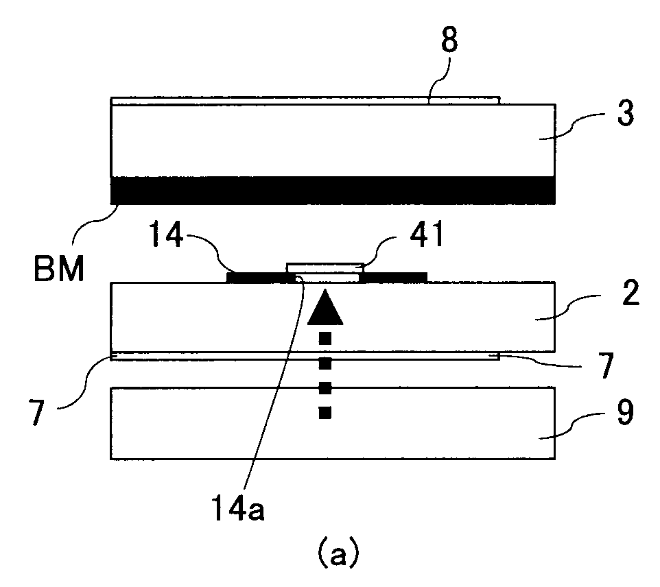
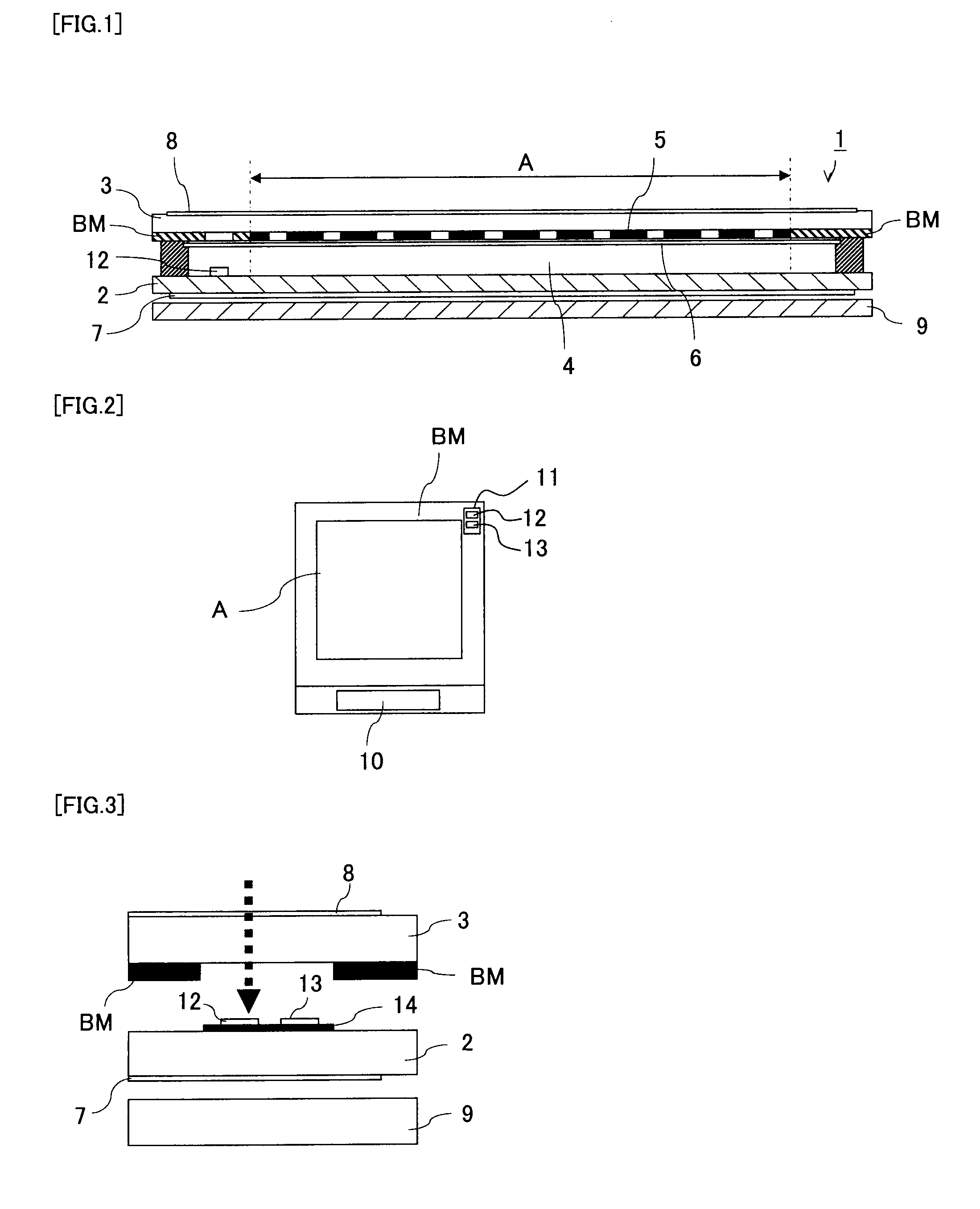
[0060]FIG. 1 shows one example of a liquid crystal display device 1. In the liquid crystal display device 1, paired transparent insulation substrates constitute a liquid cell, and a liquid crystal material is sealed in the gap between the substrates to form a liquid crystal layer. Specifically, a liquid crystal layer 4 is sealed between an array substrate 2 and an opposed substr...


PUM


Abstract

A display device has a predetermined display region and includes an array substrate equipped with a drive circuit, and a light sensor for measuring outside illuminance and a temperature sensor both installed on the array substrate. A control method for the display device includes using the light sensor to measure outside illuminance and using an output of the temperature sensor to correct an output of the light sensor, thereby adjusting luminance in the display region. The display device may further include an opposed substrate in opposition to the array substrate, a liquid crystal layer sandwiched between the two substrates to form the predetermined display region, and a backlight, thereby constituting a liquid crystal display device. Another configuration of a display device has a predetermined display region and includes an array substrate equipped with a drive circuit for display, and a light sensor installed on the array substrate for measuring outside illuminance, a filtering circuit for filtering a signal output from the light sensor and a processing circuit for processing the signal output from the light sensor and then filtered with the filtering means.

Description

BACKGROUND OF THE INVENTION [0001] 1. Field of the Invention [0002] The present invention relates to a display device, such as a liquid crystal display device, and to a control method therefor and particularly to an improvement in a display device equipped with a light sensor for monitoring outside illuminance. [0003] 2. Description of the Related Art [0004] As display devices for information equipment including personal computers and word processors and for image equipment including television sets, camcorders and car navigation systems, liquid crystal display devices having features of lightweight, small thickness and low power consumption have widely been used. In the liquid crystal display devices, in order to realize a bright display screen, major devices adopt a configuration having a built-in backlight irradiating illuminating light from behind a display element. [0005] One of the merits the liquid crystal display devices have is the property of low power consumption. General...

Claims


Application Information

Patent Timeline
Patent Type & Authority Applications(United States)
IPC IPC(8): G01J1/44
CPCG01J1/02G01J1/0252G01J1/42G09G2360/144G01J2001/4247G09G3/3406G01J1/46
Inventor NAKAMURA, TAKASHIHAYASHI, HIROTAKATADA, NORIONAKAMURA, HIROKI
Owner JAPAN DISPLAY CENTRAL CO LTD
Why Eureka
Try Eureka