Voltage Monitor and Electrical Storage Device Using the Same

Inactive Publication Date: 2008-01-03
PANASONIC CORP
View PDF2 Cites 10 Cited by
  • Summary
  • Abstract
  • Description
  • Claims
  • Application Information

AI Technical Summary

Benefits of technology

[0007] The object of the present invention is therefore providing a voltage monitor capable of easily detecting a short-circuit that occurs between adjacent input terminals, even when each divided voltage, which is detected at a connecting point of resistors, is fed into the input terminals disposed at a narrow intervals. The voltage monitor of the present invention detects the voltage applied to the both ends of each of first and the second capacitors which an electrical storage device contains at least and are connected in series. The voltage monitor has a charging circuit configured to apply voltage to the electrical storage device, a monitoring section and a controller. The monitoring section includes a first voltage-dividing section, a first input-terminal, a second voltage-dividing section, a second input-terminal and a selector switch. The first voltage-dividing section divides a voltage at a connecting point of the first and the second capacitors by a plurality of resistors. The divided voltage obtained at the first voltage-dividing section is fed into the first input-terminal. The second voltage-dividing section divides a voltage of the second capacitor on a side of a charging circuit by a plurality of resistors. The plurality of resistors takes a resistance value so that the second voltage-dividing section outputs a divided voltage different from that obtained by the first volta

Problems solved by technology

This can be a cause of an inaccurate detection of the divided voltage of each capacitor.
However, the above-mentioned connecting method is not efficient, since the input terminals are alternately connected to output and ground, so that

Method used


Image

  • Voltage Monitor and Electrical Storage Device Using the Same
  • Voltage Monitor and Electrical Storage Device Using the Same
  • Voltage Monitor and Electrical Storage Device Using the Same

Examples


first exemplary embodiment

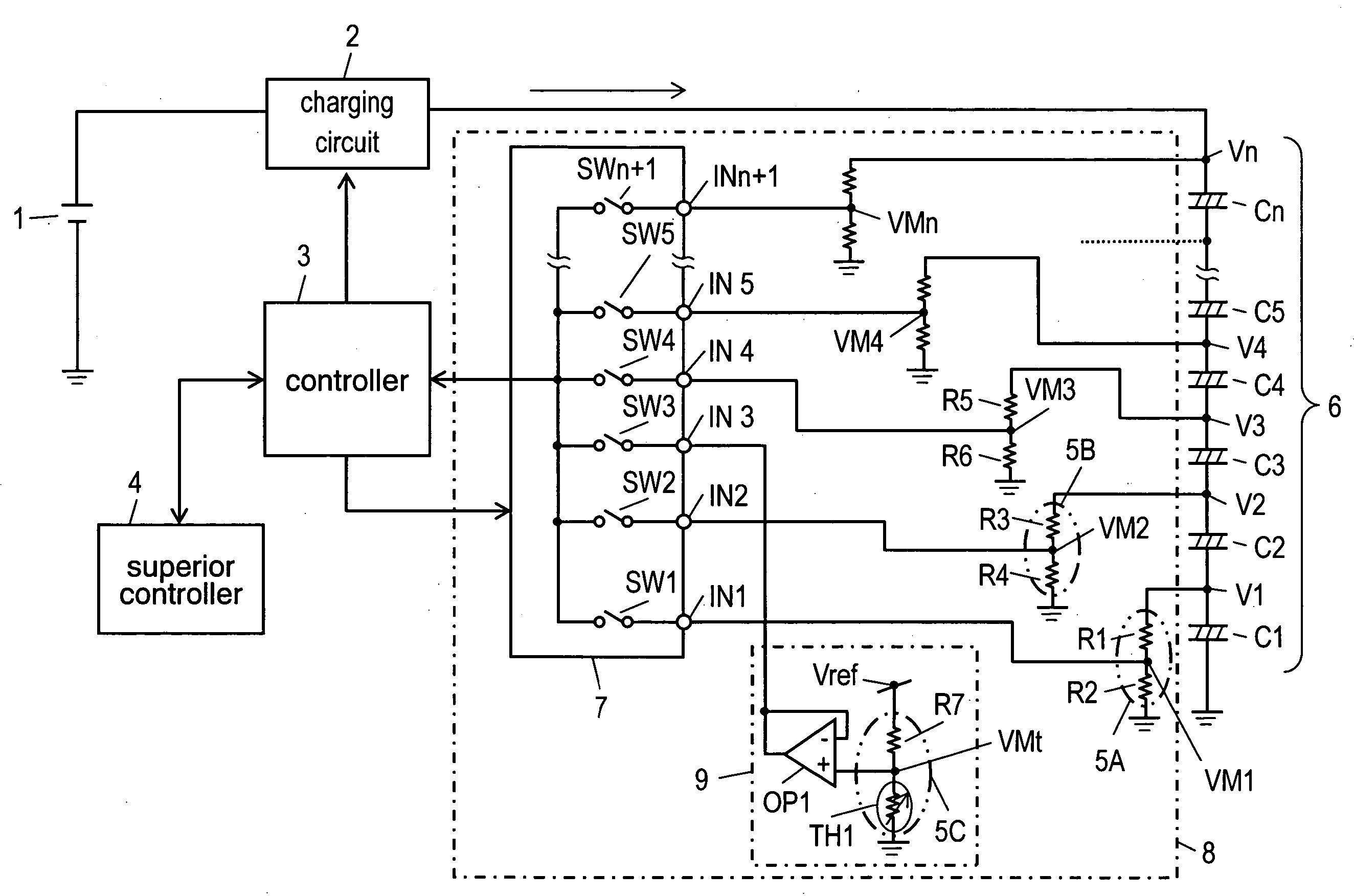
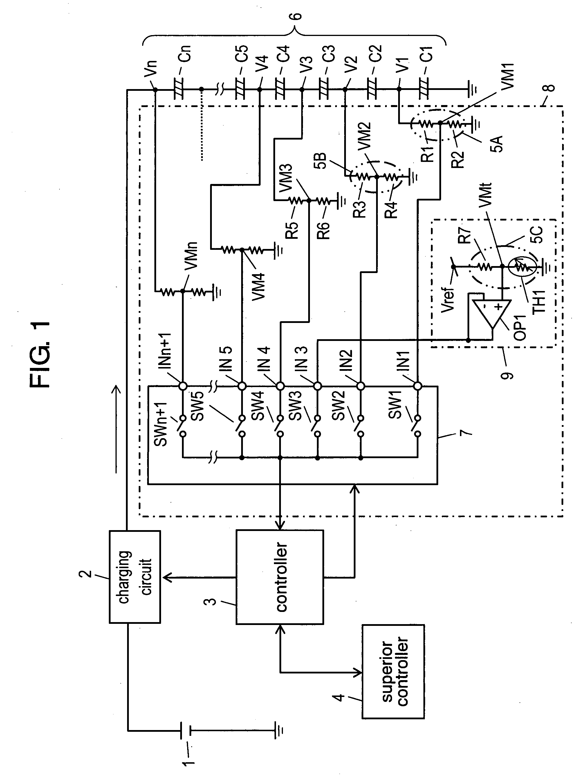
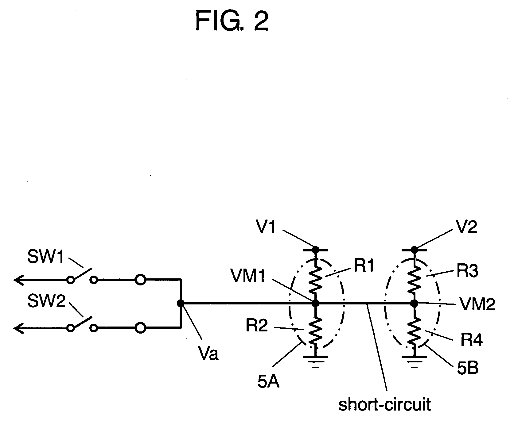
[0020]FIG. 1 is a circuit block diagram containing a voltage monitor in accordance with a first exemplary embodiment of the present invention. FIG. 2 is an equivalent circuit diagram when a short-circuit has occurred between input terminals of the voltage monitor of the present exemplary.

[0021] Main power supply 1, which is formed of a battery or a generator, is connected to charging circuit 2. Charging circuit 2 controls charging voltage and charging current at each predetermined value. Charging circuit 2 receives operation instructions to start or stop charging from controller 3. As described later, controller 3 controls whole of the voltage monitor, and communicates with superior controller 4 to determine the start and stop of charging.

[0022] Storage section 6 is formed of electrical double layer capacitors C1 through Cn (n represents the number of capacitors) connected in series. With the use of resistors R1 and R2, voltage-dividing section 5A as a first voltage-dividing secti...

second exemplary embodiment

[0054]FIG. 3 is a circuit diagram containing a voltage monitor in accordance with a second exemplary embodiment of the present invention. FIG. 4 is an equivalent circuit diagram when a short-circuit has occurred between an input terminal that receives the output of divided voltage at a divided voltage section and an input terminal that receives the output of temperature at a temperature-detecting section in the voltage monitor. FIGS. 5A through 5C are charts showing time-varying characteristics of the voltage of the voltage monitor. FIG. 5A shows time-varying characteristics of the voltage at a connecting point of capacitors under normal condition of the voltage monitor. FIG. 5B shows time-varying characteristics of the voltage at a connecting point of capacitors when a short-circuit has occurred between the input terminals under the condition where the output voltage of temperature at the temperature-detecting section is higher than the output of divided voltage at the voltage-divi...

third exemplary embodiment

[0070]FIG. 6 is a circuit diagram showing the temperature-detecting section of a voltage monitor in accordance with the third exemplary embodiment. FIG. 7 is a partial circuit diagram showing a state in which output of divided voltage is selected when a short-circuit has occurred between the input terminal that receives the output of divided voltage at a voltage-dividing section and the input terminal that receives the output of temperature at the temperature-detecting section in the voltage monitor.

[0071] The structure of the embodiment differs from the structure of FIG. 3 in the second embodiment in employing temperature-detecting section 9A having the circuit structure of FIG. 6. The rest of the structure is almost the same as that in the second embodiment; accordingly, like parts have same reference marks and in-detail description thereof will be omitted. The description below will be focused on the different section.

[0072] According to the structure of the second embodiment, ...


PUM


Abstract

In a voltage monitor that measures voltages applied to the terminals of each of a plurality of capacitors constituting a storage section, the each voltage applied to a connecting point between terminals of the capacitors in charging operation, is divided by resistors and the divided voltage is fed into a selector switch. The resistance values used for dividing the each voltage are determined in advance so that a short-circuit between adjacent input terminals of the selector switch allows the divided voltage to have a voltage shift remarkably larger or smaller than the divided voltage obtained under the normal charging operation.

Description

RELATED APPLICATIONS [0001] This application is the U.S. National Phase under 35 U.S.C. § 371 of International Application No. PCT / JP2006 / 316481, filed on Aug. 23, 2006, which in turn claims the benefit of Japanese Application Nos. 2005-243850 filed on Aug. 25, 2005 and 2005-309355 filed on Oct. 25, 2005, the disclosures of which Applications are incorporated by reference herein.TECHNICAL FIELD [0002] The present invention relates to a voltage monitor used for an electrical storage device that employs a plurality of capacitors arranged in series connection or in series-parallel connection. BACKGROUND ART [0003] In a conventional electrical storage device using a plurality of electrical double layer capacitors arranged in series connection, terminal voltage of each capacitor is detected through the following process. Each pair of two resistors connected in series is connected between each of the connecting points of capacitors, i.e., each terminal, and ground. The voltage at the conn...

Claims


Application Information

Patent Timeline
IPC IPC(8): G01R19/00G01R19/32H02J7/02
CPCH02J7/0019G01R31/3658G01R31/396
Inventor ODAJIMA, YOSHIMITUMORITA, KAZUKITAKEMOTO, JUNJI
Owner PANASONIC CORP
Why Eureka
Try Eureka