Vehicle Headlight

a headlight and vehicle technology, applied in the field of vehicle headlights, can solve the problems of insufficient collecting power, poor distance visibility, and the inability of conventional vehicle headlights to provide an insufficient light distribution to the side of the vehicle, and achieve the effect of reducing the loss of light intensity based on reflection

Inactive Publication Date: 2008-01-03
STANLEY ELECTRIC CO LTD
View PDF2 Cites 6 Cited by
  • Summary
  • Abstract
  • Description
  • Claims
  • Application Information

AI Technical Summary

Benefits of technology

[0015]To be yet more specific, the presently disclosed subject matter can include a vehicle headlight which can use light projected from a light source more effectively than in the case of typical lights that block light that is projected from the light source and directed above a horizontal level in front of the vehicle headlight.
[0024]In other words, the vehicle headlight can be configured to take into account the fact that the frequency of use of the light in low beam mode is typically higher than that of the light in high beam mode. The elliptic reflecting surface of the first reflector and the reflecting surface of the second reflector are thus configured to provide the maximum output during low beam illumination, and part of the light that is to be projected toward a direction below the horizontal level during low beam illumination is reflected and projected above the horizontal level during high beam illumination. Consequently, it is possible to project a low beam and a high beam in a more reasonable and efficient fashion as compared to lamp configurations in which a maximum output is obtained during high beam illumination (which is low in frequency of use).
[0025]In particular, the vehicle headlight according to an aspect of the presently disclosed subject matter can use the light projected from the light source more effectively than in the case of blocking the light that is projected from the light source that is directed to a location above the horizontal level in front of the vehicle headlight.
[0029]Consequently, as compared to the case of projecting only the refracted light that passes through the inner lens to the direction of projection of the vehicle headlight, the vehicle headlight can increase the angle of diffusion of the light to be projected in the direction of projection of the vehicle headlight and improve the use efficiency of the light as well.
[0032]In a vehicle headlight according to still another aspect of the presently disclosed subject matter, it is possible to increase the angular range of diffusion of the light that is to be projected in the direction of projection of the vehicle headlight as compared to the case where the light from the light source is not collected before passing through the inner lens.
[0035]Consequently, as compared to the case where all the light emitted from the light source is reflected twice or more before being projected in the direction of projection of the vehicle headlight, the vehicle headlight with the above-described first and fourth reflectors can reduce reflection-based loss in light intensity and can thus project bright light in the direction of projection of the vehicle headlight.

Problems solved by technology

In such cases, the resulting vehicle headlights may have insufficient collecting power and poor distant visibility.
Nevertheless, conventional vehicle headlights have only been capable of providing an insufficient light distribution to sides of vehicles.
Conventional vehicle headlights have also had the problem that when the vehicle headlights are viewed from the front of the vehicle, the corners of the vehicle headlights are not filled with the illumination light, i.e., the corners drop in luminance.
Put another way, however, this configuration cannot effectively use the light that is projected from the light source that is directed upward in front of the vehicle.
Equivalently, the conventional vehicle headlights including those disclosed in the above publication can switch between a low beam distribution pattern and a high beam distribution pattern for light illumination, but cannot project a low beam and a high beam in a reasonable or efficient fashion.

Method used


Image

  • Vehicle Headlight
  • Vehicle Headlight
  • Vehicle Headlight

Examples


Embodiment Construction

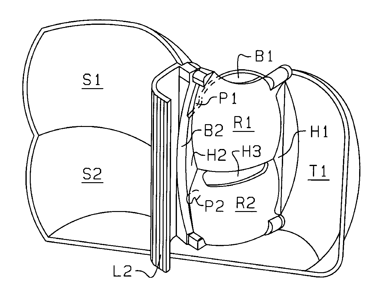
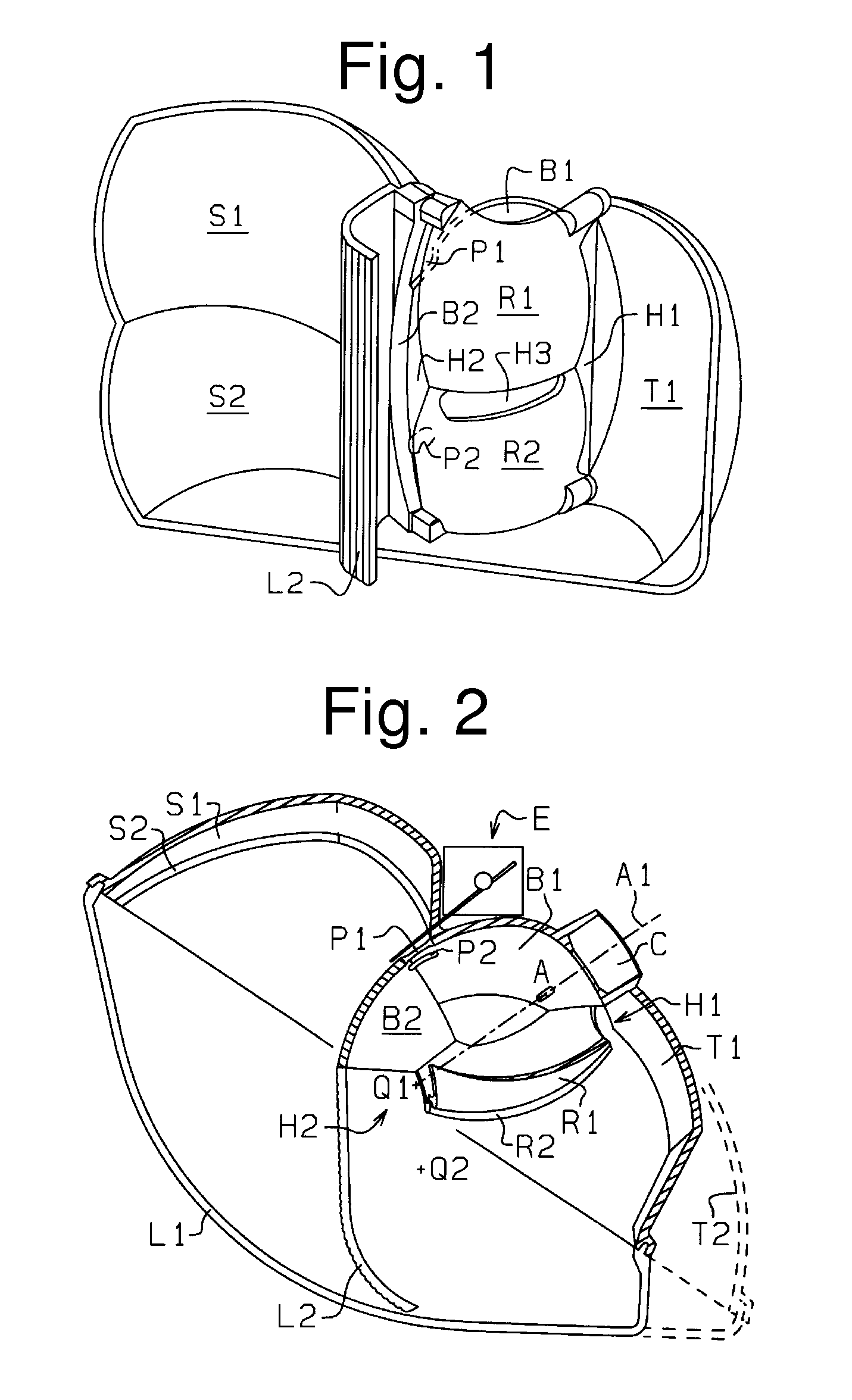
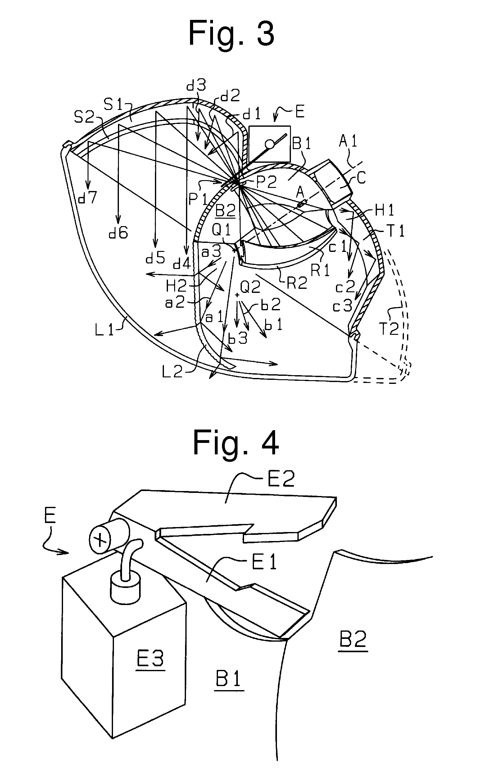
[0047]Hereinafter, exemplary embodiments of vehicle headlights made in accordance with principles of the presently disclosed subject matter will be described. FIG. 1 is a perspective view of an exemplary embodiment of a vehicle headlight made in accordance with principles of the disclosed subject matter. FIG. 2 is a sectional view of the vehicle headlight shown in FIG. 1, taken along a horizontal plane. FIG. 3 is a diagram showing the optical paths of light that are projected from the vehicle headlight as shown in FIG. 2.

[0048]In the embodiment shown in FIG. 1, directional characteristics with respect to the vehicle headlight shall be expressed in terms of the top, bottom, right, and left in a front view of the same. For the vehicle, directional characteristics shall be expressed in terms of the front, rear, right, and left with reference to the forward direction of the vehicle. Descriptions as to the top, bottom, right, and left on the drawings will be added as appropriate.

[0049]Th...


PUM


Abstract

A vehicle headlight can project a low beam and a high beam in a reasonable and efficient fashion and does not require a maximum output during high beam illumination, which is low in frequency of use. A light source can be arranged so that a main optical axis thereof forms an angle of approximately 30° to 60° with respect to a front-to-back direction of a vehicle / vehicle headlight. An extremity of the light source can extend toward the front and side of the vehicle. Part of a first reflector can be arranged closer to the front and a center of the vehicle than the light source. A second reflector can be configured to collect light from the first reflector and reflect the same light to the front of the vehicle. The second reflector can be located behind and closer to the side of the vehicle than the light source is. A distribution pattern switching unit can be located between the first reflector and the second reflector. The first reflector and the second reflector can be configured to provide a maximum output during low beam illumination. Part of the light from the first reflector that is to be projected to the lower half of the low beam distribution pattern during low beam illumination can be reflected by a reflecting plate of the distribution pattern switching unit and projected towards a location above a horizontal level during high beam illumination.

Description

[0001]This application claims the priority benefit under 35 U.S.C. § 119 of Japanese Patent Application No. 2006-178832 filed on Jun. 28, 2006, which is hereby incorporated in its entirety by reference.BACKGROUND[0002]1. Technical Field[0003]The presently disclosed subject matter relates to a vehicle headlight which is arranged to wrap around from the front to a side of a vehicle. Furthermore, the presently disclosed subject matter relates to a vehicle headlight which can project a low beam and a high beam in a consistent and efficient fashion and can utilize the light projected from a light source more effectively than in conventional cases.[0004]2. Description of the Related Art[0005]In view of improved distant visibility, it has been desirable for conventional vehicle headlights to use a reflector having high collecting power. This, however, entails greater depth dimensions and lateral width dimensions for the vehicle headlights.[0006]In the meantime, the space at both sides of t...

Claims


Application Information

Patent Timeline
Patent Type & Authority Applications(United States)
IPC IPC(8): F21V7/08F21Y101/00
CPCF21S48/1773F21S48/1388F21S41/172F21S41/285F21S41/321F21S41/365F21S41/43F21S41/686
Inventor OYAMA, HIROO
Owner STANLEY ELECTRIC CO LTD
Why Eureka
Try Eureka