
Image processing apparatus for identifying an individual object, image processing method, and storage medium

a technology of image processing and individual objects, applied in the field of image recognition techniques, can solve the problems of difficult to efficiently and accurately identify an individual, and achieve the effect of accurately identifying an individual object in an imag

Active Publication Date: 2008-01-03
CANON KK
View PDF7 Cites 68 Cited by
  • Summary
  • Abstract
  • Description
  • Claims
  • Application Information

AI Technical Summary

Benefits of technology

[0008]The present invention has been made in consideration of the above-described problem, and has as its object to provide a technique of more accurately identifying an individual object in an image.

Problems solved by technology

In the above-described prior arts, however, it is difficult to efficiently and accurately identify an individual while coping with various states related to the poses, expressions, and illumination conditions of objects (e.g., identical persons) in the same class even when both the number of states and the number of individuals to be identified increase.

Method used


Image

  • Image processing apparatus for identifying an individual object, image processing method, and storage medium
  • Image processing apparatus for identifying an individual object, image processing method, and storage medium
  • Image processing apparatus for identifying an individual object, image processing method, and storage medium

Examples


first embodiment

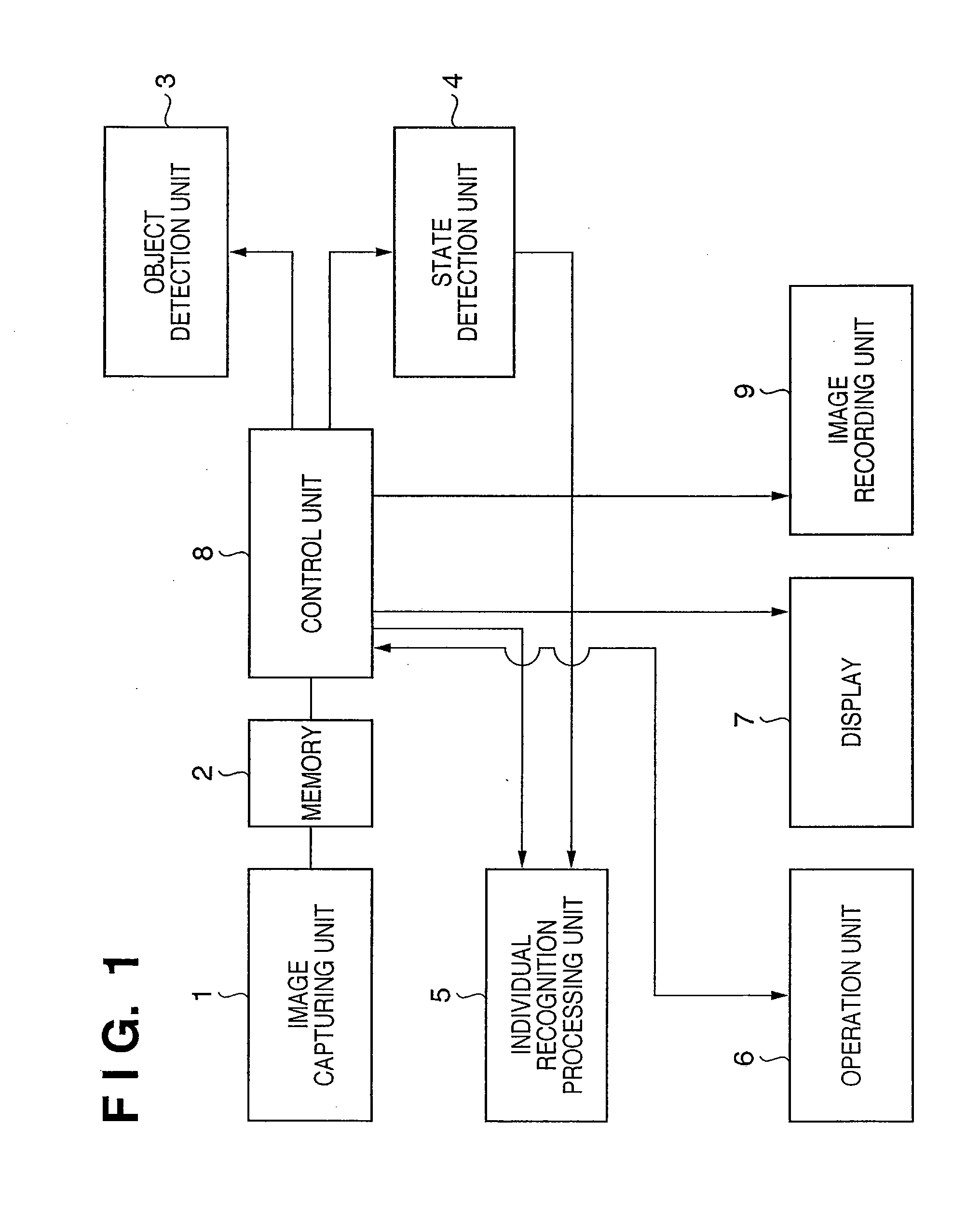
[0031]FIG. 1 is a block diagram showing the functional arrangement of an image processing apparatus according to this embodiment.

[0032]An image capturing unit 1 includes imaging optics such as lenses, an image sensor typically formed from a CCD or CMOS image sensor, a sensor signal processing circuit, and a sensor driving circuit. External light is converted into an electrical signal via the imaging optics and image sensor. Upon receiving a reading control signal from the sensor driving circuit, the image sensor outputs, to a memory 2, an image signal (e.g., a signal obtained by sub-sampling and block reading) designated by the control signal. That is, an image captured by the image capturing unit 1 is sent to the memory 2 as data. In this way, each frame (captured image) of a moving image captured by the image capturing unit 1 is sent to the memory 2.

[0033]The memory 2 stores image data sent from the image capturing unit 1 and various kinds of data to be used for processes to be de...

second embodiment

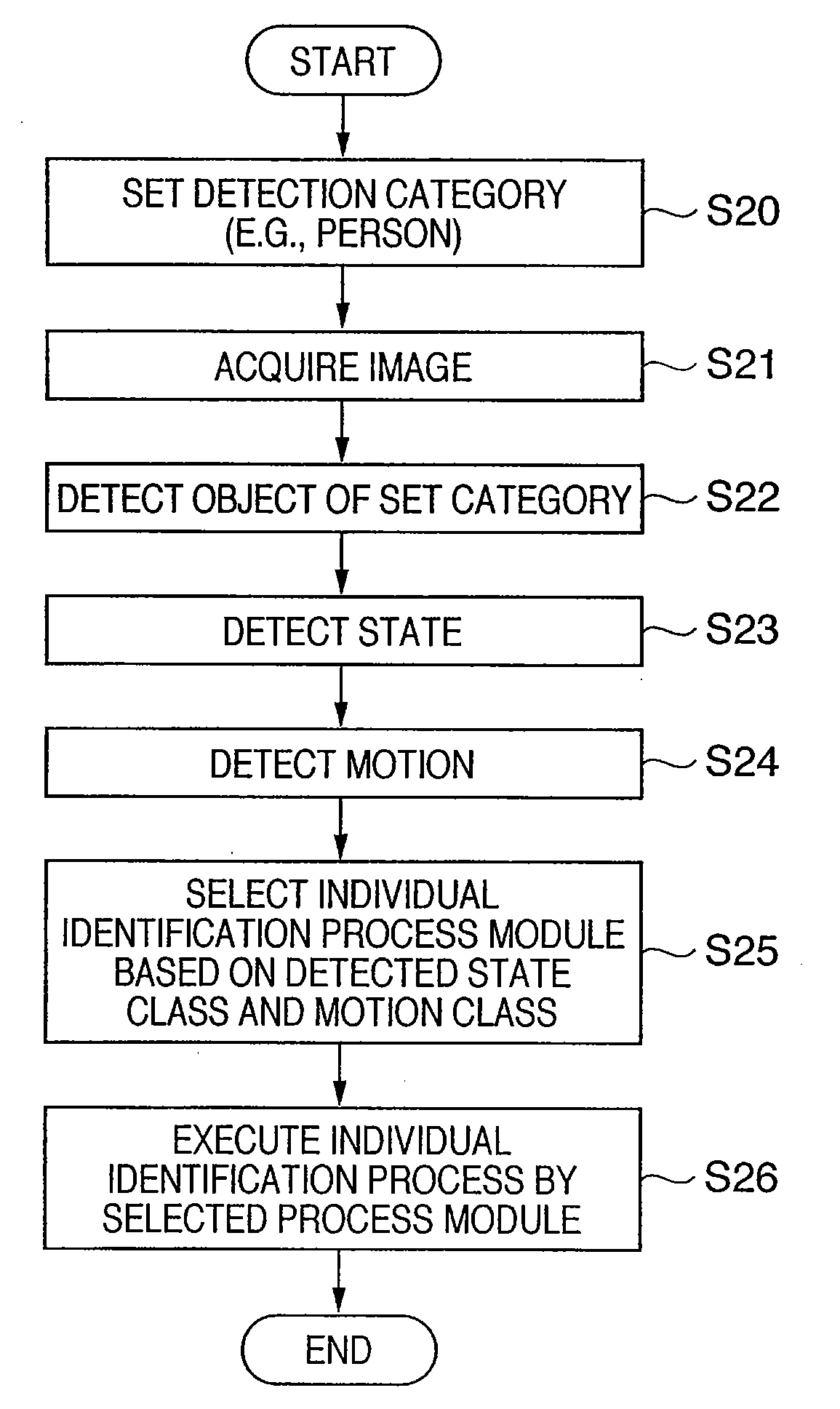
[0080]The second embodiment is different from the first embodiment in that the pattern of a time series change of a state class detected in the first embodiment is detected as a state class (motion class) representing (the contents of) a specific motion pattern of an object (person), and individual identification is executed in the motion state class.

[0081]FIG. 5 is a block diagram showing the functional arrangement of an image processing apparatus according to this embodiment. The arrangement shown in FIG. 5 is obtained by adding a motion detection unit 35 to the arrangement shown in FIG. 1. An image capturing unit 21, memory 22, control unit 28, object detection unit 23, state detection unit 24, individual recognition processing unit 25, operation unit 26, display 27, and image recording unit 29 shown in FIG. 5 are the same as the image capturing unit 1, memory 2, control unit 8, object detection unit 3, state detection unit 4, individual recognition processing unit 5, operation u...


PUM


Abstract

An image capturing unit acquires an image including an object. A state detection unit detects the state of the object in the image. An individual recognition processing unit determines one of a plurality of individual identification process modules in correspondence with the state detected by the state detection unit. The individual recognition processing unit executes, for the object in the image, an individual identification process by the determined individual identification process module.

Description

BACKGROUND OF THE INVENTION[0001]1. Field of the Invention[0002]The present invention relates to an image recognition technique, especially, to technique for identifying an individual object.[0003]2. Description of the Related Art[0004]A technique of recognizing an object under various conditions is disclosed in Japanese Patent Laid-Open No. 10-275237. Japanese Patent Laid-Open No. 10-275237 discloses a recognition technique that executes model fitting by detecting a moving region in an image and fitting a geometric model in that region.[0005]A technique disclosed in Japanese Patent Laid-Open No. 2003-263639 registers face images corresponding to various facial directions in advance, calculates the collation scores of an input image with respect to the images of faces in the respective directions, selects a deformation parameter corresponding to a direction with a high collation score, converts the inputted image into a frontal face by using the selected deformation parameter, and c...

Claims


Application Information

Patent Timeline
IPC IPC(8): G06K9/00
CPCG06K9/00248G06K9/00315G06K9/00261G06V40/165G06V40/167G06V40/176
Inventor MATSUGU, MASAKAZUMORI, KATSUHIKOSUZUKI, TAKASHI
Owner CANON KK
Features
  • Generate Ideas
  • Intellectual Property
  • Life Sciences
  • Materials
  • Tech Scout
  • Unparalleled Data Quality
  • Higher Quality Content
  • 60% Fewer Hallucinations
Learn More