Fixing apparatus

a technology of fixing rollers and fixing rollers, which is applied in the direction of electrographic process apparatus, instruments, optics, etc., can solve the problems of inability to transfer the amount of heat necessary for fixing the toner image onto the recording paper sheet, the surface temperature of the fixing rollers is prone to drop for increases in the transport speed or processing speed, and the inability to fix the toner image accurately. to achieve the effect of accurately controlling the surface temperature of the fixing rollers

Inactive Publication Date: 2008-01-03
SHARP KK
View PDF4 Cites 15 Cited by
  • Summary
  • Abstract
  • Description
  • Claims
  • Application Information

AI Technical Summary

Benefits of technology

[0014]An object of the present invention is to provide a fixing apparatus by which it is possible to always appropriately control the surface temperature of the fixing rollers without applying a large load on the heat source or the control circuits thereof or on the rotational mechanism or the like of the fixing rollers.

Problems solved by technology

However, when switching the transport speed or processing speed for the sheet of recording paper in this manner, the surface temperature of the fixing rollers tends to drop for increases in the transport speed or processing speed for the sheet of recording paper, which makes deficiencies in fixing of the toner image onto the sheet of recording paper more likely to occur.
This is because a pass-through time of the sheet of recording paper passing through a nip region between the hot roller and the pressure roller becomes shorter for increases in the transport speed or processing speed for the sheet of recording paper, and the amount of heat necessary for fixing the toner image onto the sheet of recording paper cannot be transferred between the sheet of recording paper and the rollers such that deficiencies occur in the fusing of the toner onto the sheet of recording paper.
As a result, reductions in print quality are incurred.
However, in cases where the surface temperature of the fixing rollers is controlled by bringing a heating belt or an external hot roller into contact with the fixing rollers as in the above-mentioned JP 2004-198659A and JP 2004-85601A, when the surface temperature of the fixing rollers drops along with increases in the transport speed or processing speed for the sheet of recording paper as described above, the temperature of the heat source of the heating belt or the external hot roller or the like must be raised quickly to suppress drops in the surface temperature of the fixing rollers, and this increases the load on the heat source itself and the control circuits for the heat source.
Furthermore, since the contact surface area between the heating belt or the external hot roller and the fixing roller is kept constant, the heat of the heating belt or external hot roller will not always be conducted quickly to the fixing rollers even when the temperature of the heating belt or external hot roller is raised, which makes it difficult to control the surface temperature of the fixing rollers.
For this reason, it is conceivable to widen the contact surface area between the heating belt or the external hot roller and the fixing roller to improve the thermal conduction between these, but doing this involves permanently increasing the resistance against the rotation of the fixing rollers, which increases the load on the rotational mechanism or the like of the fixing rollers.

Method used


Image

  • Fixing apparatus
  • Fixing apparatus
  • Fixing apparatus

Examples


Embodiment Construction

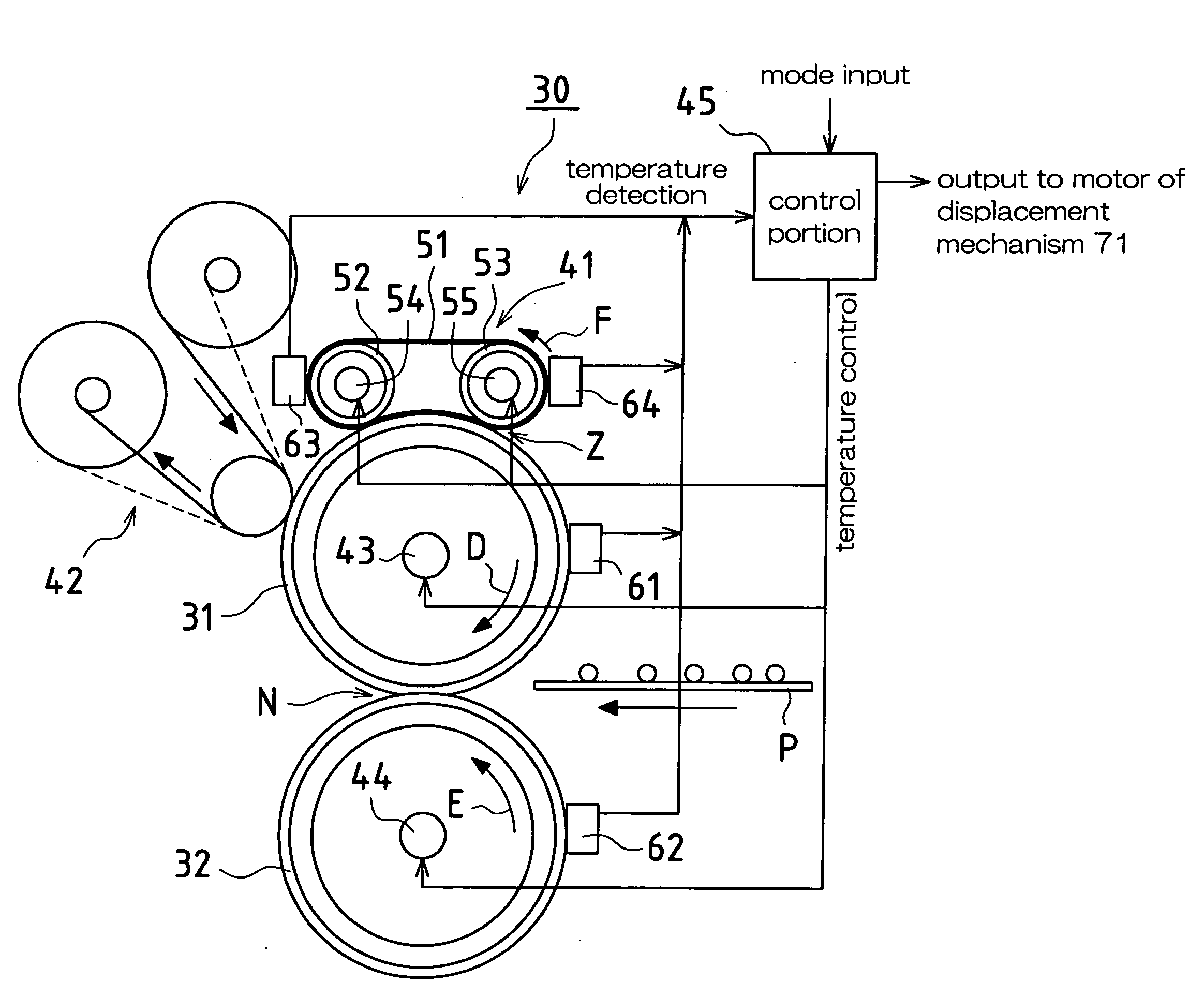
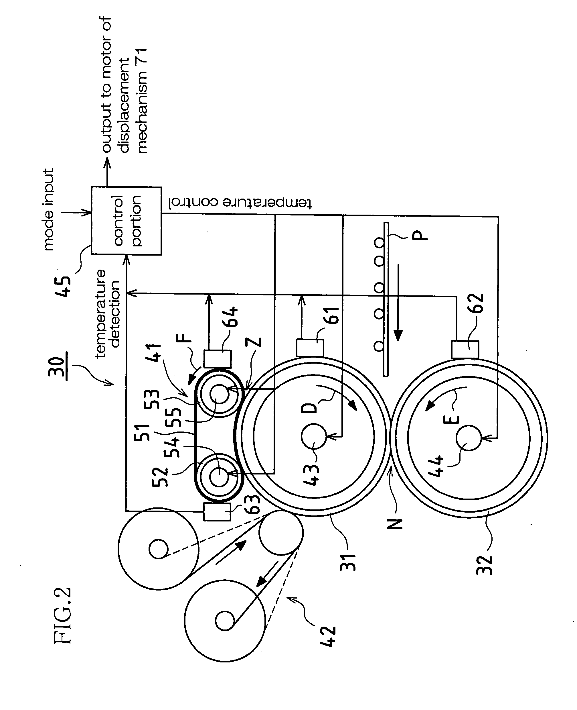
[0051]Hereinafter, an embodiment of the present invention is described in detail with reference to the accompanying drawings.

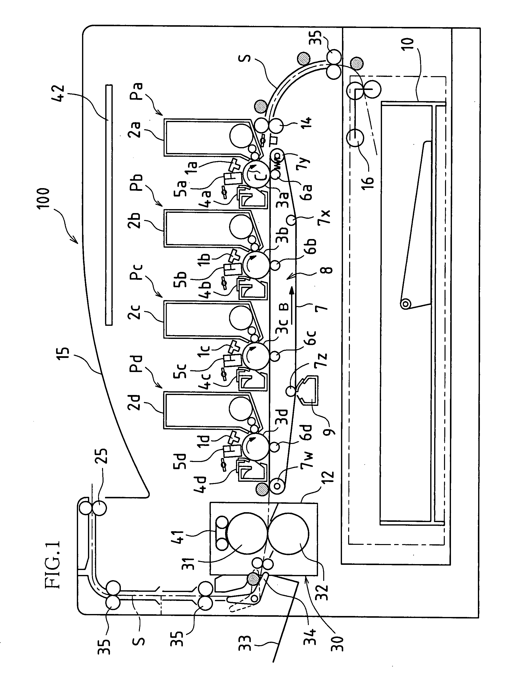
[0052]FIG. 1 is a cross-sectional view that schematically illustrates an image forming apparatus 100 viewed laterally in which one embodiment of a fixing apparatus according to the present invention has been applied. The image forming apparatus 100 receives image data that has been transmitted in from the outside and forms on a sheet of recording paper a color or a monochrome image indicated by that image data.

[0053]In the image forming apparatus 100, color image data is handled by being indicated as an image made up of black (K), cyan (C), magenta (M), and yellow (Y) colors, and for images made up of other colors, the image data is first subjected to a process in which the other colors are converted to black, cyan, magenta, and yellow, then the image data is used.

[0054]The image forming apparatus 100 is provided with components such as image forming stations ...


PUM


Abstract

In one embodiment, in a standby mode, an endless heating belt is caused to move apart from a hot roller. Furthermore, in color mode, the endless heating belt is caused to contact the hot roller to make possible thermal conduction between the endless heating belt and the hot roller, and a surface temperature of the endless heating belt is adjusted within a prescribed range of 200° C. to 210° C. being higher than a fixing temperature of 180° C. Further still, in monochrome mode, a length (or a surface area) of a heating contact region between the endless heating belt and the hot roller is set to a maximum to increase a thermal conduction efficiency between the endless heating belt and the hot roller, and a surface temperature of the endless heating belt is adjusted within a prescribed range of 210° C. to 220° C. being sufficiently higher than the fixing temperature of 180° C.

Description

CROSS REFERENCE TO RELATED APPLICATIONS[0001]This application claims priority under 35 U.S.C. § 119(a) on Patent Application No. 2006-179962 filed in Japan on Jun. 29, 2006, the entire contents of which are hereby incorporated by reference.BACKGROUND OF THE INVENTION[0002]1. Field of the Invention[0003]The present invention relates to fixing apparatuses that are applied in electrophotographic image forming apparatuses such as copiers, facsimile machines, and printers.[0004]2. Description of the Related Art[0005]Generally, in image forming apparatuses such as copiers, printers, and facsimile machines, an electrostatic latent image is formed on a photosensitive body, toner is supplied from a development apparatus to the photosensitive body, and a toner image is formed on the photosensitive body by the electrostatic latent image on the photosensitive body being developed by the toner. Thereafter, the toner image is transferred from the photosensitive body to a sheet of recording paper,...

Claims


Application Information

Patent Timeline
Patent Type & Authority Applications(United States)
IPC IPC(8): G03G15/20
CPCG03G2215/2016G03G15/2064
Inventor MINAKUCHI, YASUNORITATEISHI, YOSHINOBUMIKITA, TOSHIYAYAMASHITA, MICHIHIRO
Owner SHARP KK
Why Eureka
Try Eureka