
Belt feeding device and image heating device

Inactive Publication Date: 2008-01-03
CANON KK
View PDF4 Cites 20 Cited by
  • Summary
  • Abstract
  • Description
  • Claims
  • Application Information

AI Technical Summary

Benefits of technology

[0014]Accordingly, it is a principal object of the present invention to provide a belt feeding device which can stabilize and feed the belt while suppressing the deterioration of the belt.
[0015]It is another object of the present invention to provide an image heating device which can stabilize and feed the belt while suppressing the deterioration of the belt.

Problems solved by technology

Therefore, in such the fixing device, the belt disengages from a roller which supports the belt, or the end of the belt is damaged due to the snaking movement of the belt, and in order to prevent these defects, the problem of the snaking movement of the belt has been one of the important technical problems.
In the case of above described “swing-type-control”, the belt will always move in the widthwise direction thereof, the belt slides relative to a stretching rollers and fixing roller with this movement with the possible result of deteriorations of these members.
When the “swing-type-control” stated above in the fixing device using a fixing belt and a pressing belt as disclosed in Japanese Laid-open Patent Application 2004-341346 is employed, there is liability that one of the belts may give an excessive snaking force against the other one of the belts.
In other words, when the “swing-type-control” is employed for both of belts, and if the direction of the snaking force given from the other one of the belts is opposite to the direction of a snaking motion correction provided by off-set control for said one of the belts, there is liability that the snaking motion correcting force may be cancelled out.
As a result, the snaking movement may not fully be eliminated even to such an extent of the possibility that said one of the belts will shift completely, by being dragged by the other one of the belts.

Method used


Image

  • Belt feeding device and image heating device
  • Belt feeding device and image heating device
  • Belt feeding device and image heating device

Examples


embodiment 2

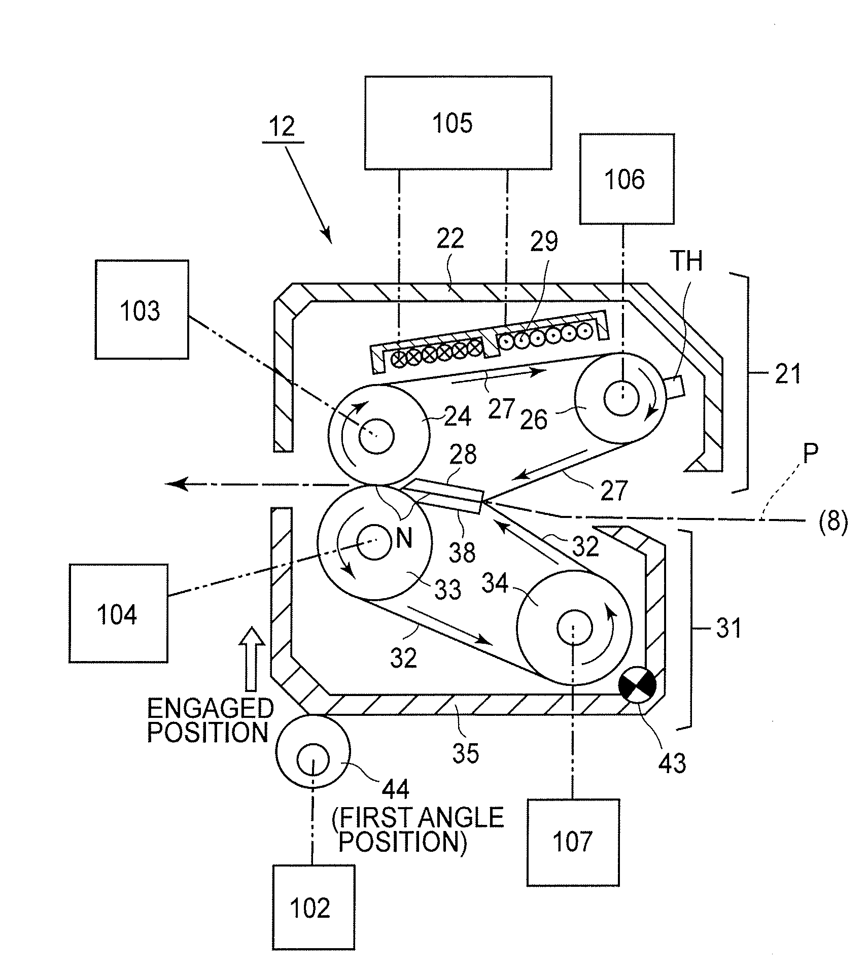
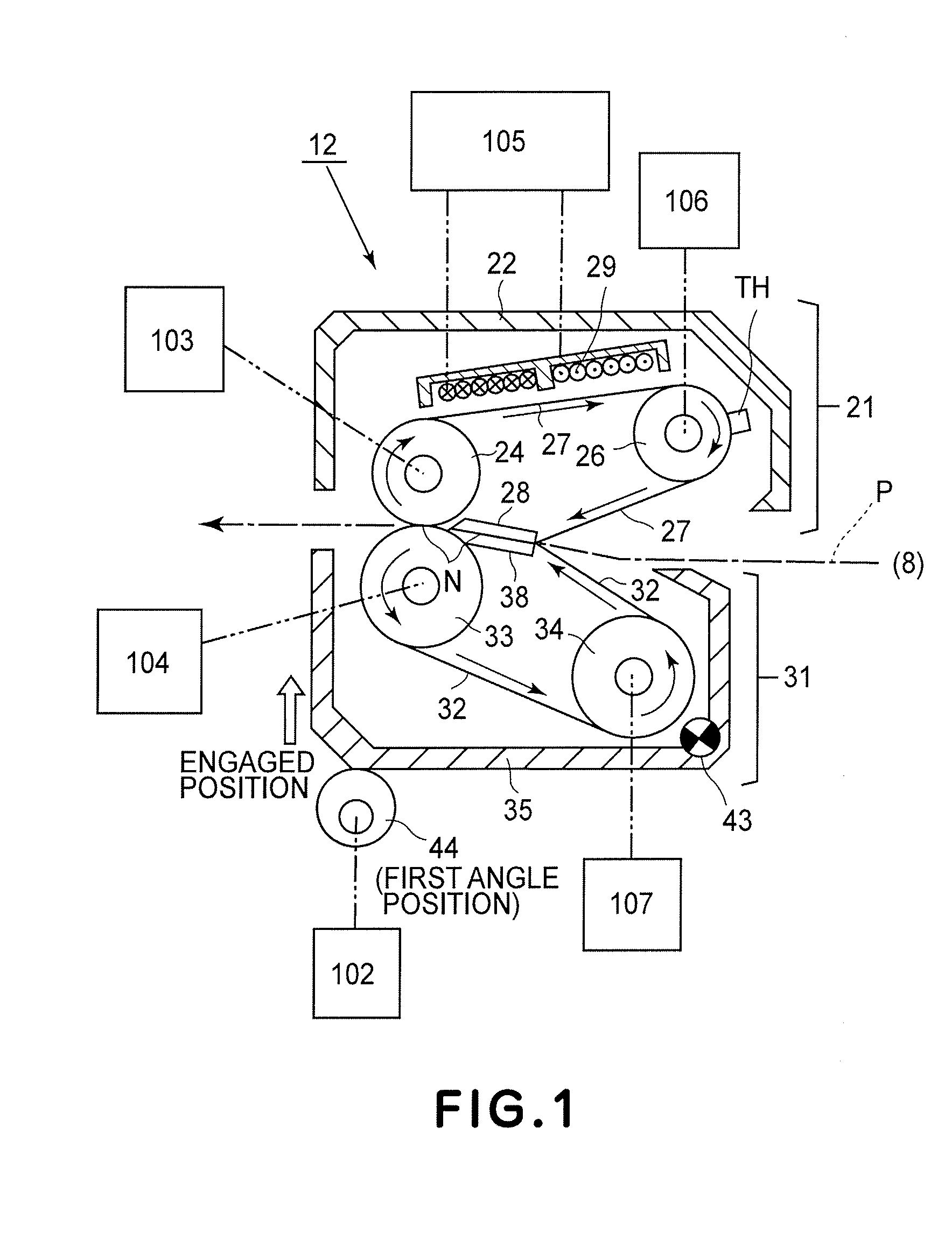
[0157]Referring to FIG. 8 which is a block diagram of the control system, the description will be made as to engagement / disengagement of the belt fixing device 12.

[0158]When the unit 21 and the unit 31 are in engagement state referring to each other as shown in FIG. 1, the fixing belt 27 and the pressing belt 32 are press-contacted to each other, so that wide fixing nip N is formed therebetween, as measured in the sheet feeding direction.

[0159]The CPU 100, during the heat fixing operation for a recording material P, controls the belt engaging and disengaging mechanism 102 to provide the engagement state forming the fixing nip N.

[0160]In addition, the CPU 100 during stand-by state of the image forming apparatus controls the belt engaging and disengaging mechanism 102, and as shown in FIG. 3, retains the disengagement state of the unit 21 and the unit 31. By this, the pressing belt 32 and the fixing belt 27 are kept in the non-contact state, so that thermal loss of the fixing belt att...


PUM


Abstract

A belt feeding apparatus includes an endless belt; a supporting member for rotatably supporting the belt; setting means for setting, when the belt is deviated from a widthwisely normal zone, an inclination angle of the supporting member to a return angle to return the belt toward the normal zone, and for setting, when a predetermined time elapses from the belt returning to the normal zone, the inclination angle of the supporting member to a balance angle to keep the belt in the zone.

Description

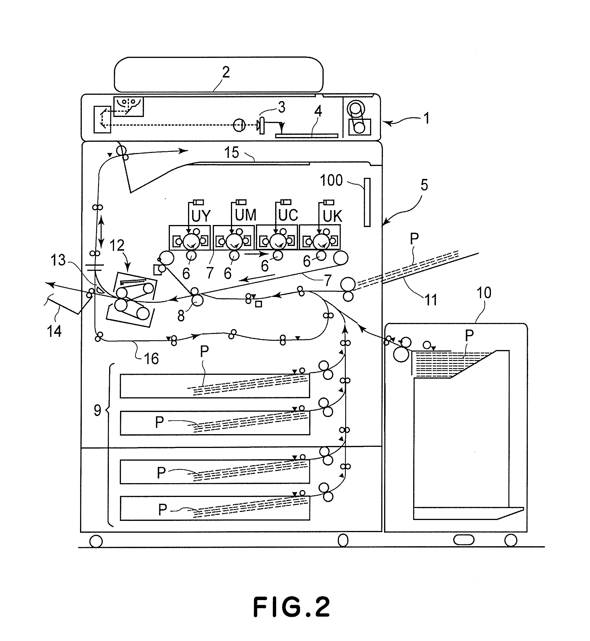
FIELD OF THE INVENTION[0001]The present invention relates to a belt feeding device for rotating an endless belt, and an image heating device using it.[0002]As such an image heating device, there are known a fixing device for fixing an unfixed image on a recording material, a glossiness increasing device for heating the image fixed on the recording material, thus increasing the glossiness of the image, and so on, for example. Such an image heating device is used in an image forming apparatus, such as a copying machine of an electrophotographic type, a printer, and a facsimile machine and so on.RELATED ART[0003]In the image forming apparatuses, such as an electrophotographic apparatus and an electrostatic recording apparatus, an unfixed toner image is formed on a sheet-like recording material, and the toner image is heated and pressed by a fixing device, so that the toner image is fixed on the recording material.[0004]Heretofore, a device of a roller type fixing device and a device of...

Claims


Application Information

Patent Timeline
IPC IPC(8): G03G15/20
CPCG03G15/2053G03G2215/2009G03G2215/2032G03G2215/2022G03G2215/2016
Inventor KUROKI, KENJIEDA, HIROYUKIFUJIMORI, TAKASHITOMIYASU, HIROAKIMATSUMOTO, HIDENORIENDO, JUNICHIKAJI, HAJIME
Owner CANON KK
Learn More