
Tool adapter

a tool and adapter technology, applied in the field of tool adapters, can solve the problems of damage to parts, complicated assembly process of this design of right angle attachment, and high cost, and achieve the effect of simple and steady structure, easy and convenient assembly

Inactive Publication Date: 2008-01-03
HOR BUNG JZYY
View PDF39 Cites 30 Cited by
  • Summary
  • Abstract
  • Description
  • Claims
  • Application Information

AI Technical Summary

Benefits of technology

[0006]The present invention has been accomplished under the circumstances in view. It is one object of the present invention to provide a tool adapter which turns the rotary driving force of a hand tool by 90 degrees to allow the hand tool to work in narrow or angled space. Moreover, the tool adapter has a steady structure that can conveniently and rapidly be assembled.
[0009]Base on the aforesaid component parts, the tool adapter has a simple and steady structure that is easy and convenient to assemble.

Problems solved by technology

Therefore, this design of right angle attachment has a complicated structure.
Further, the assembly process of this design of right angle attachment is also complicated and requires much time.
Further, during the operation of the hand tool, cutting chips may be jammed in between the output shaft and the input shaft, causing damage to the parts.

Method used


Image

  • Tool adapter
  • Tool adapter
  • Tool adapter

Examples


Embodiment Construction

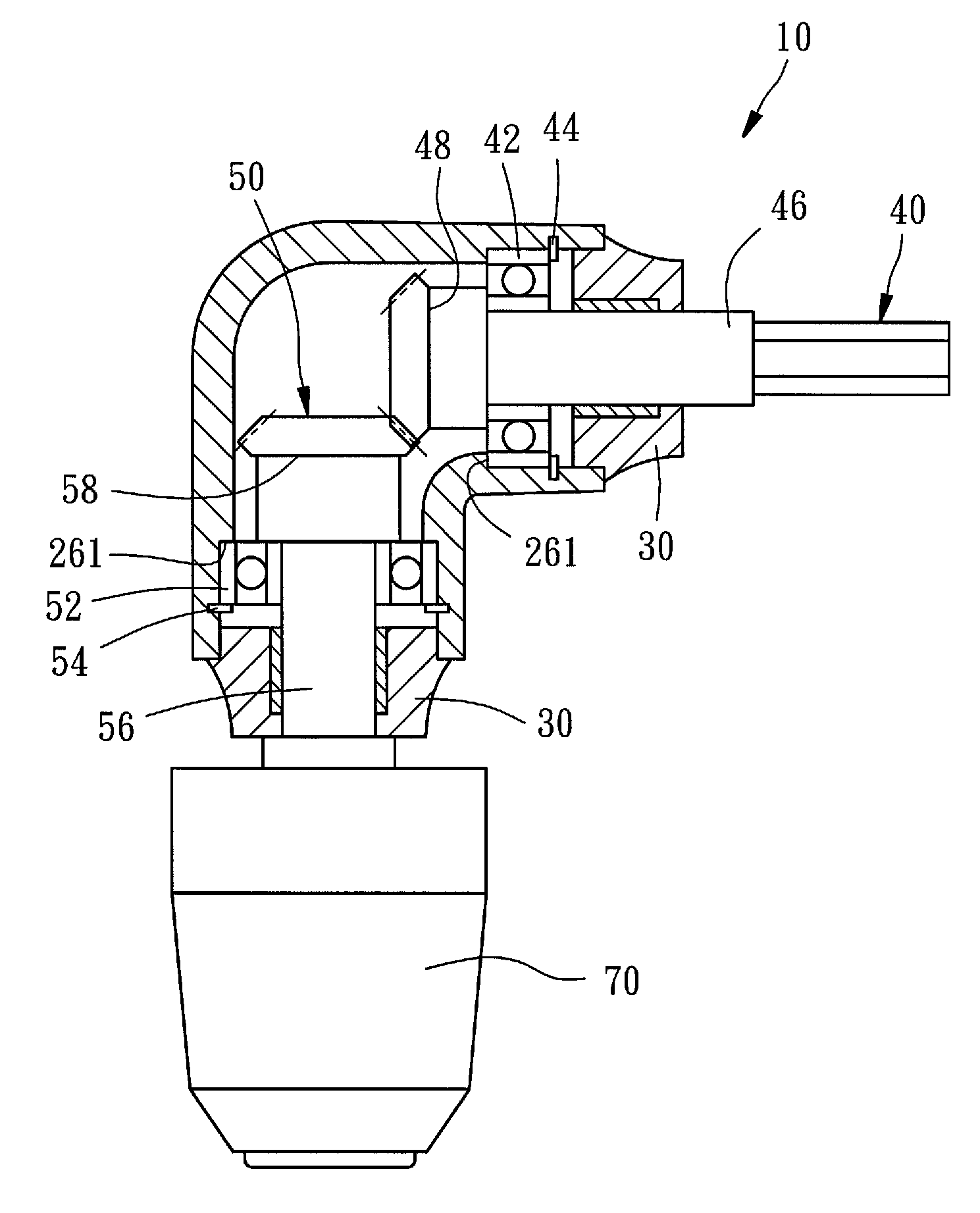
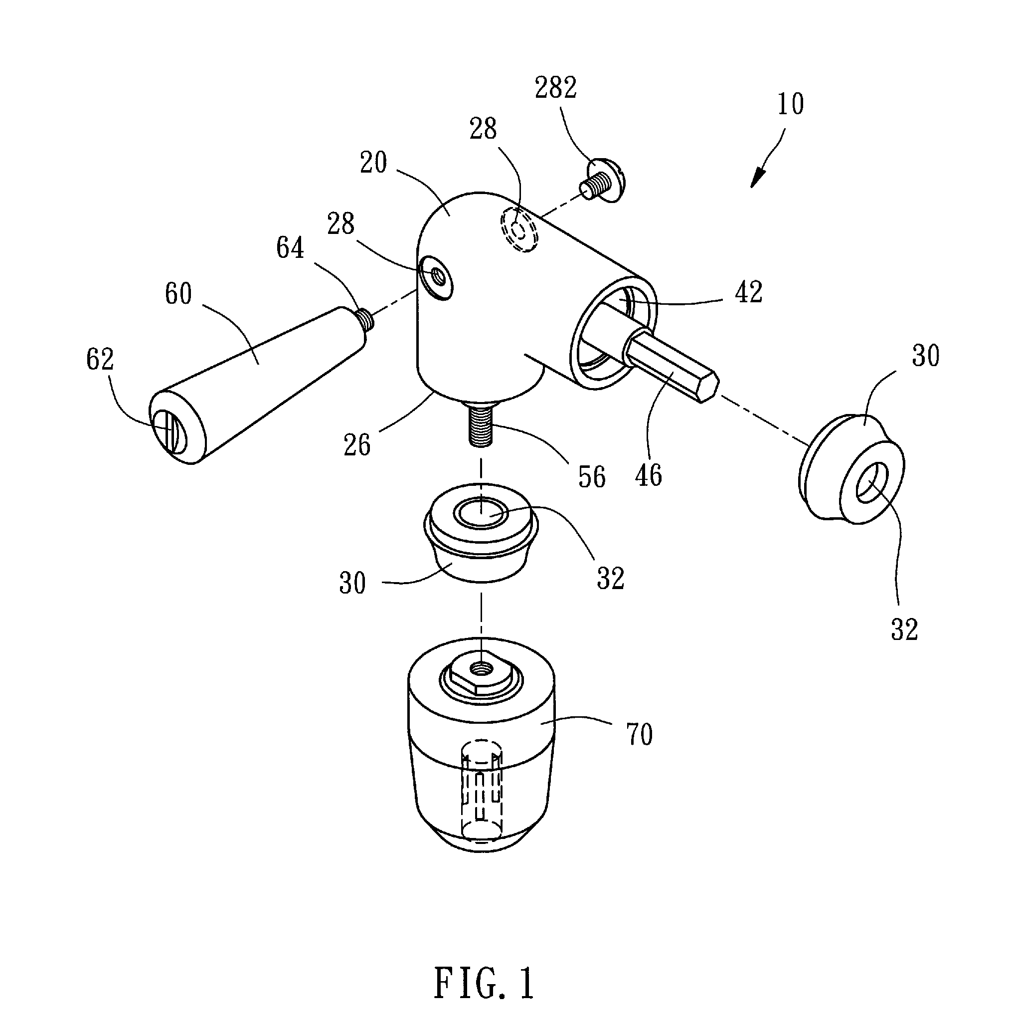
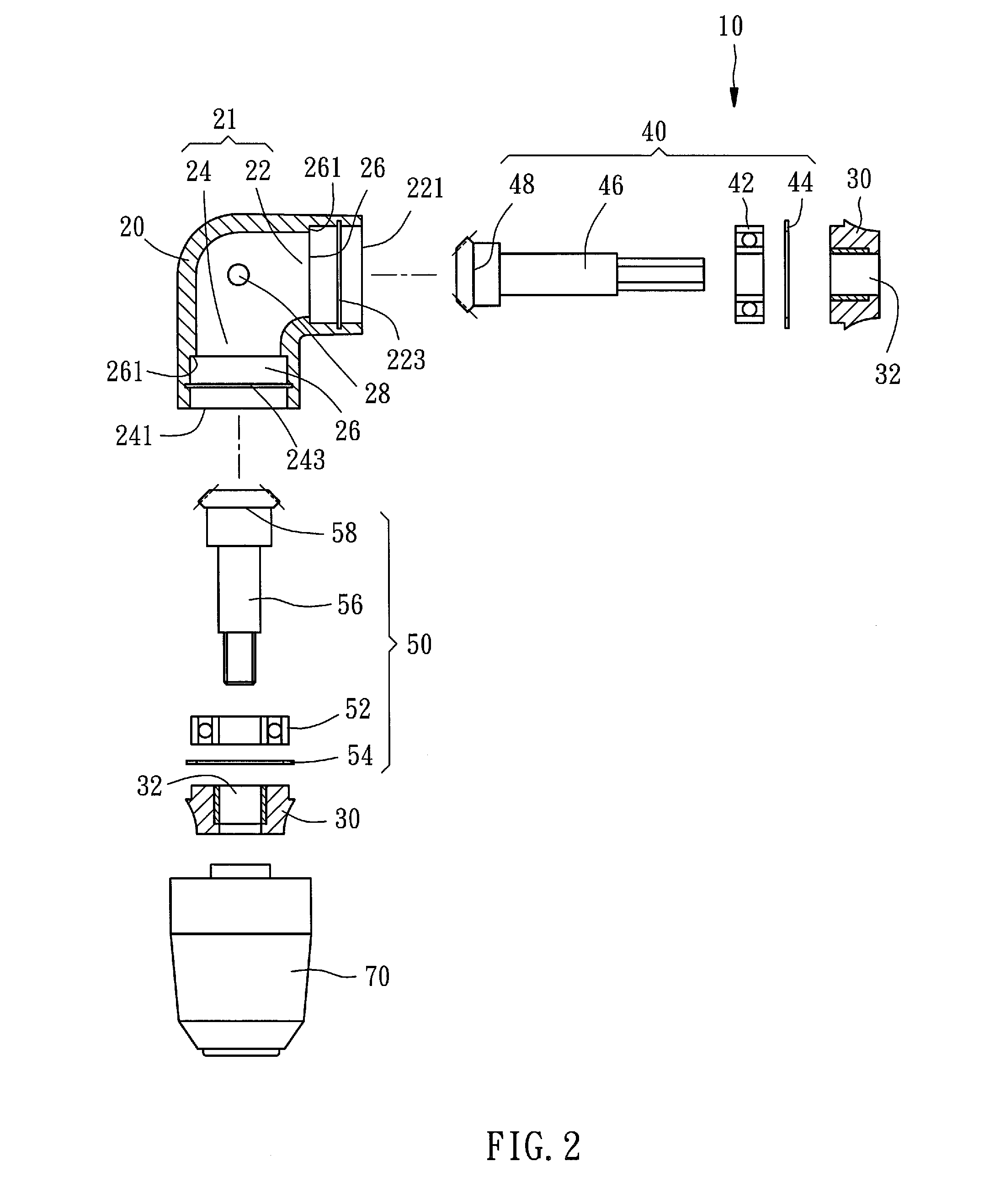
[0014]Referring to FIGS. 1 and 2, a tool adapter 10 in accordance with the present invention is shown comprised of a housing 20, two caps 30, a first connecting member 40, a second connecting member 50, a handle 60, and a chuck 70.

[0015]The housing 20 is made out of metal in one piece, having a passage 21 with a first end opening 221 and a second end opening 241. The passage 21 having a first section 22 and a second section 24 that are oriented at an approximately 90 degrees relative to each other. The first section 22 and the second section 24 are in communication with each other inside the housing 20. The housing 20 further comprises two locating portions 26 formed on the inside wall and respectively extending from the end openings 221 and 241 along the first section 22 and the second section 24, two shoulders 261 respectively formed on the inside wall adjacent to the locating portions 26, a first positioning groove 223 extending around the inside wall near the first end opening 2...


PUM

PropertyMeasurementUnit
right anglesaaaaaaaaaa
angleaaaaaaaaaa
rotary driving forceaaaaaaaaaa

Abstract

A tool adapter includes a housing, which comprises a passage with two end openings and two locating portions respectively located adjacent the two end openings, two connecting members respectively rotatably positioned in the locating portions of the housing, the connecting members each having a shaft respectively extended out of the end openings and an engagement portion respectively engaged with each other, and two locating devices respectively mounted in the housing to secure the connecting members to the housing.

Description

BACKGROUND OF THE INVENTION[0001]1. Field of the Invention[0002]The present invention relates generally to a tool adapter for hand tool and, more particularly, to a tool adapter which turns the rotary driving force of a hand tool by 90 degrees to allow the hand tool to work in narrow or angled space, and which is easy to assemble.[0003]2. Description of the Related Art[0004]U.S. Pat. No. 6,463,824 discloses a right angle attachment configured to be attached to a small electrically powered rotary hand tool. The attachment has a flexible input shaft and an output shaft. In operation, the attachment is easily attached to the hand tool by merely removing the chuck that is a part of the original hand tool and attaching the chuck to the attachment output shaft, threadably engaging a driver nut on the rotary tool output shaft, engaging a mounting coupling assembly onto a threaded end of the rotary tool case, and fitting the attachment to the hand tool by merely sliding it into engagement a...

Claims


Application Information

Patent Timeline
Patent Type & Authority Applications(United States)
IPC IPC(8): B23B45/00
CPCY10T408/65B25F5/001
Inventor HOR, BUNG-JZYY
Owner HOR BUNG JZYY
Learn More