Inlet throttle controlled liquid pump with cavitation damage avoidance feature

a technology of cavitation damage and liquid pump, which is applied in the direction of liquid fuel engine, machine/engine, positive displacement liquid engine, etc., can solve the problems of cavitation erosion, and inability to control the pump

Active Publication Date: 2008-01-03
CATERPILLAR INC
View PDF17 Cites 19 Cited by
  • Summary
  • Abstract
  • Description
  • Claims
  • Application Information

AI Technical Summary

Problems solved by technology

When the cavitation bubbles collapse adjacent a surface, cavitation erosion can occur.
In some instances, cavitation erosion can occur at undesirable locations, such as the inlet port passage.
Depending upon where the cavita

Method used


Image

  • Inlet throttle controlled liquid pump with cavitation damage avoidance feature
  • Inlet throttle controlled liquid pump with cavitation damage avoidance feature
  • Inlet throttle controlled liquid pump with cavitation damage avoidance feature

Examples


Embodiment Construction

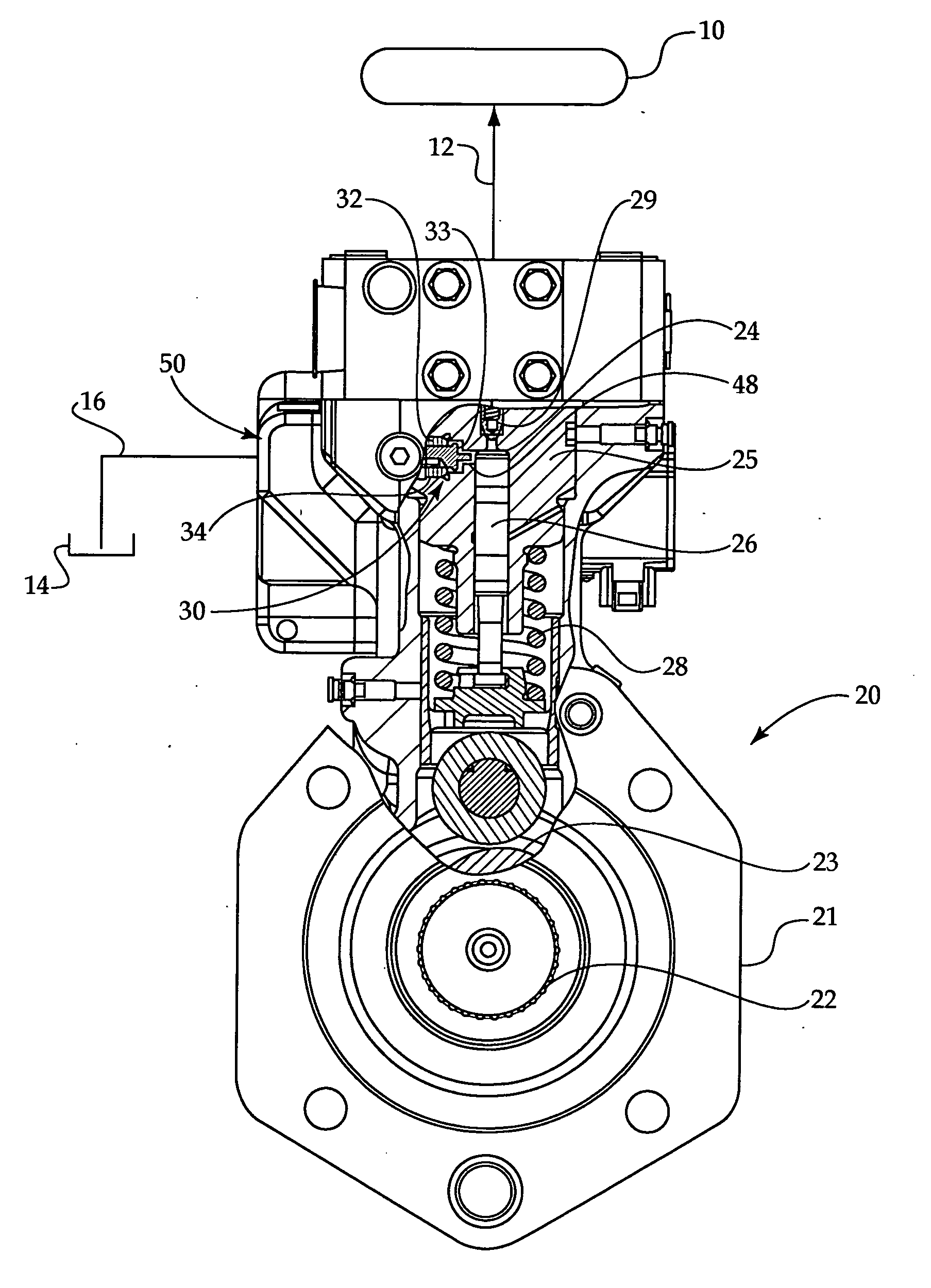
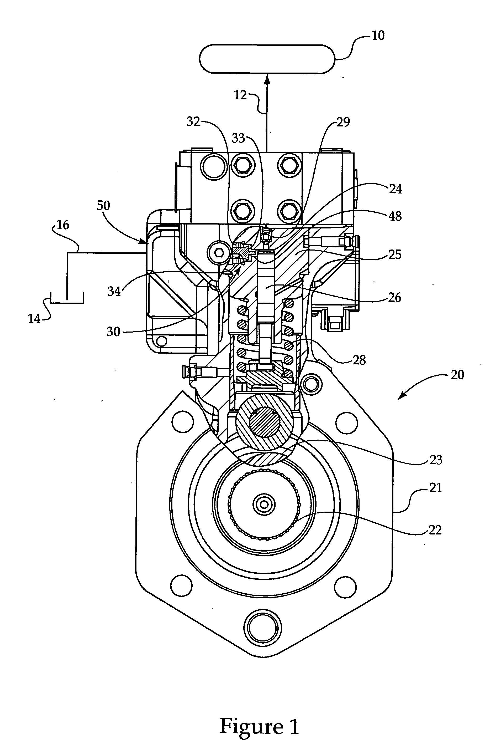
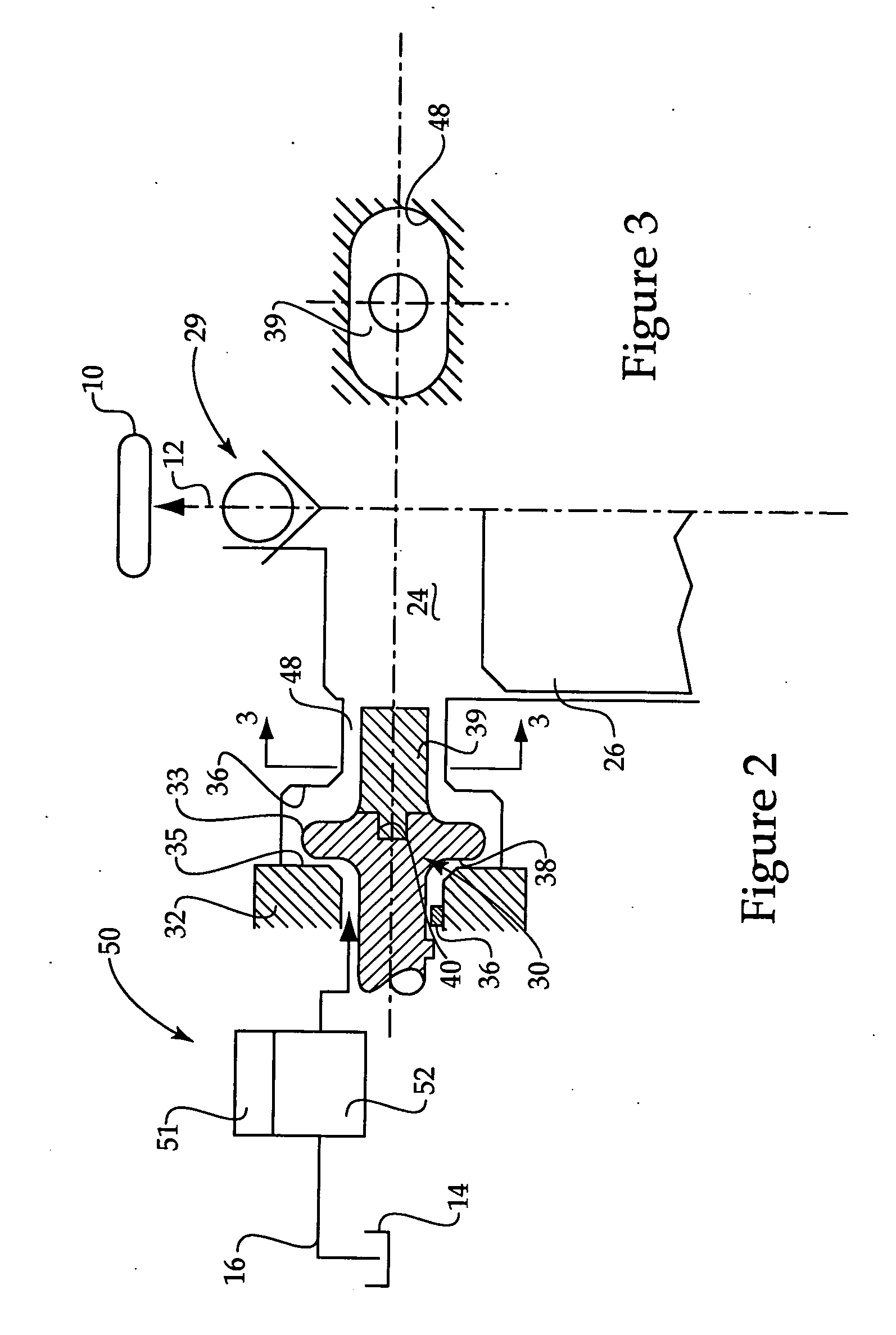
[0017]In some liquid systems, such as a high pressure common rail fuel system of FIG. 1, a high pressure reservoir or common rail 10 receives high pressure liquid fuel from a liquid pump 20 via an outlet flow passage 12. Pump 20 draws fuel from low pressure reservoir 14 via an inlet supply passage 16 in a conventional manner. Pump 20 includes a pump body 21 within which a drive shaft 22 rotates by being driven in a conventional manner, such as via a conventional gear train coupled to an internal combustion engine. With each rotation of drive shaft 22, a cam 23 having one or more lobes rotates. Like many similar pumps, pump body 21 includes a barrel 25 that defines a plunger cavity 24 within which a plunger 26 reciprocates in response to rotation of cam 23. A return spring 28 maintains plunger 26 at a position that follows cam 23 in a conventional manner. Thus, with each rotation of cam 23 and the corresponding reciprocation of plunger 26, the plunger reciprocates through a fixed tra...


PUM


Abstract

A liquid pump includes an electronically controlled throttle inlet valve to control pump output. With each reciprocation cycle, a plunger displaces a fixed volume of fluid. When less than this fixed volume is desired as the output from the pump, the electronically controlled throttle inlet valve throttles flow past a passive inlet check valve to reduce output. As a consequence, cavitation bubbles are generated during the intake stroke. Cavitation damage to surfaces that define the inlet port passage are avoided by a specifically shaped and sized cavitation flow adjuster extending from the valve member of the passive inlet check valve. By positioning the cavitation flow adjuster in the inlet port passage, a flow pattern is formed in a way to encourage cavitation bubble collapse away from surfaces that could result in unacceptable cavitation damage to the pump.

Description

TECHNICAL FIELD[0001]The present disclosure relates generally to liquid pumps with output control via a throttle inlet valve, and more particularly to an inlet check valve that includes a cavitation flow adjuster to reduce cavitation damage in the pump.BACKGROUND[0002]In one class of high pressure liquid pumps, output from the pump is controlled by throttling the inlet with an electronically controlled metering valve. As a consequence, cavitation bubbles are generated when the output of the pump is controlled to be less than the volume displaced with each reciprocation of the pump plunger. One application for such a pump is in a fuel system that utilizes a common rail and a high pressure fuel pump to pressurize the rail. In this specific example, the pump is driven directly by the engine, and the output from the pump is controlled by changing the inlet flow area via the inlet throttle valve.[0003]When the inlet throttle valve reduces the flow area to the plunger cavity, cavitation b...

Claims


Application Information

Patent Timeline
IPC IPC(8): F04B19/00
CPCF04B49/225F04B11/0091F02M59/205F02M59/34F02M59/464F02M2200/04Y10T137/7784
Inventor TIAN, YESTOCKNER, ALAN R.MACK, DAVID C.
Owner CATERPILLAR INC
Why Eureka
Try Eureka