Laser-produced implants

a three-dimensional structure and laser-produced technology, applied in the direction of shoulder joints, prostheses, manufacturing tools, etc., can solve the problems of high cost and time consumption of procedures, and the field has not focused on reducing the density of three-dimensional structures or growing a porous surfa

Active Publication Date: 2008-01-03
UNIV OF LIVERPOOL +2
View PDF99 Cites 209 Cited by
  • Summary
  • Abstract
  • Description
  • Claims
  • Application Information

AI Technical Summary

Problems solved by technology

This procedure can be extremely expensive and time consuming.
In addition, each implant must be made separately and requires it's own casting device, which is usually destroyed when removing the completed implant.
But while the field of rapid prototyping has focused on increasing density of such three-dimensional structures, the field has not focused its attention on reducing the density of three-dimensional structures or growing a porous surface with a denser surface.

Method used


Image

  • Laser-produced implants
  • Laser-produced implants
  • Laser-produced implants

Examples


Embodiment Construction

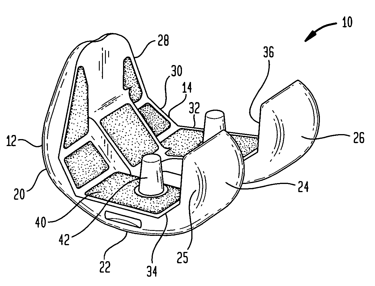
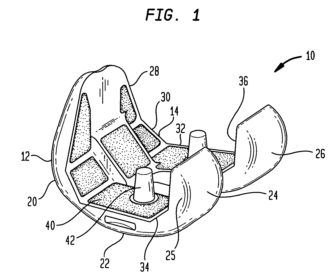
[0029] The present invention relates to a method of forming an implant to be positioned in vivo during surgery, especially an orthopedic implant that replaces a joint, such as a knee joint, hip joint or shoulder joint. Although the present invention will be described with reference to a femoral component, the exemplified element should in no way be perceived as a limiting feature.

[0030] As used herein, the following directional definitions apply. Anterior and posterior mean nearer the front or nearer the back of the body respectively. Thus, for the knee joint described herein, anterior refers to that portion of the knee that is nearer the front of the body, when the leg is in an extended position. Proximal and distal mean nearer to or further from the root of the structure, respectively. For instance, the distal femur is part of the knee joint further from the hip joint while the proximal femur is closer to the hip joint. Finally, the adjectives medial and lateral mean nearer the s...


PUM

PropertyMeasurementUnit
porosityaaaaaaaaaa
speedaaaaaaaaaa
forceaaaaaaaaaa

Abstract

A method of producing an orthopedic implant including the steps of building a flat open model of at least a portion of an implant. The flat open model may be built using a selective laser center process. The flat open model preferably includes at least one groove along either a first surface or a second surface of the model. Next a force may be applied to the flat open model at predetermined locations to thereby cause the model to bend and assume a shape similar to a desired result. The now bent model may be resurfaced by either applying additional material such that the bent flat open model assumes the shape of a desired implant or the bent open model may be snap fit to an additional element.

Description

CROSS-REFERENCE TO RELATED APPLICATIONS [0001] This application claims the benefit of the filing date of U.S. Provisional Patent Application No. 60 / 755,260 filed Dec. 30, 2005, the disclosure of which is hereby incorporated herein by reference.BACKGROUND OF THE INVENTION [0002] The present invention relates to a method of making a three-dimensional structure utilizing a flat substrate. [0003] In particular, this invention relates to a computer-aided laser apparatus or other suited high energy beam, which sequentially remelts a plurality of powder layers to build a porous layer in a layer-by-layer fashion. The porous layer may be attached to an implant that may be created using a similar method. [0004] Currently, implants such as femoral implants are constructed using various dies and casting processes. This procedure can be extremely expensive and time consuming. In addition, each implant must be made separately and requires it's own casting device, which is usually destroyed when r...

Claims


Application Information

Patent Timeline
Patent Type & Authority Applications(United States)
IPC IPC(8): A61F2/38
CPCA61F2/30767B22F3/1055A61F2/30942A61F2/32A61F2/3859A61F2/40A61F2002/30878A61F2002/3092A61F2002/30968A61F2002/3097A61F2002/30971A61F2002/30985A61F2310/00023A61F2310/00029A61F2/3094B22F5/10B33Y10/00B33Y80/00Y02P10/25B22F10/28B22F10/62B22F10/38B22F12/49B22F10/36B22F10/66B22F10/366B22F10/32
Inventor O'NEILL, WILLIAMSUTCLIFFE, CHRISTOPHER J.JONES, ERIC
Owner UNIV OF LIVERPOOL
Why Eureka
Try Eureka