
Device comprising a combination of a chamber and a piston

a technology of a combination and a chamber is applied in the field of a combination of a chamber and a piston, which can solve the problems of limiting the use of the pump to persons of a certain height, giving the user a wrong feeling, and directly loading the arms or legs of the user of the pump, so as to reduce the operating force, reduce the investment and operational costs, and be reliable and inexpensive

Inactive Publication Date: 2008-01-10
VAN DER BLOM NICOLAAS
View PDF6 Cites 12 Cited by
  • Summary
  • Abstract
  • Description
  • Claims
  • Application Information

AI Technical Summary

Benefits of technology

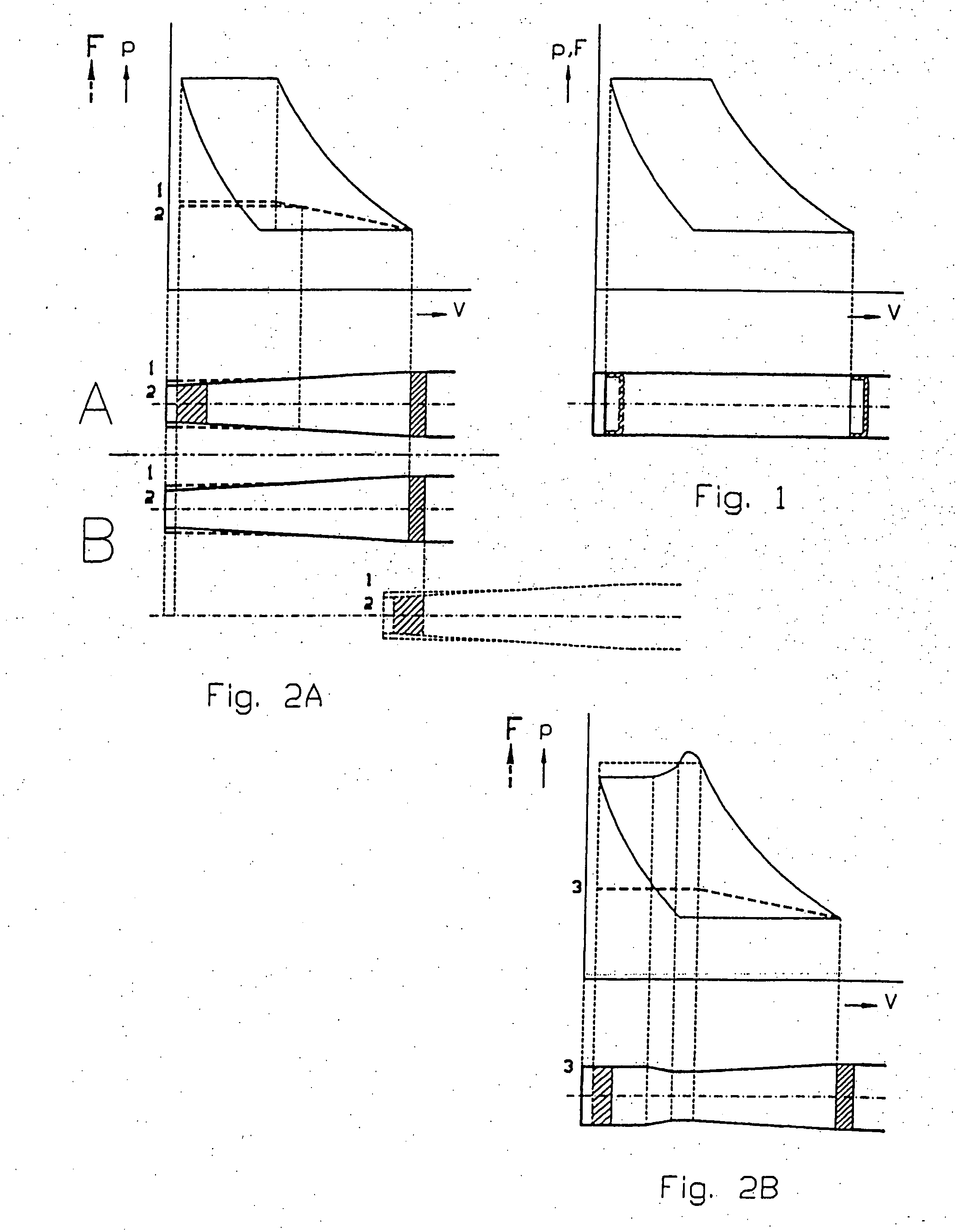
[0006] The object of the invention is to provide a reliable and inexpensive device comprising a combination of a chamber and a piston, to which its design has to comply to specific demands towards the operating force. These devices can be specifically be piston pumps but also devices like actuators, shock absorbers or motors etc. Manually operated piston pumps will be comfortable to use by the target group without compromising pumping time, while devices which are not manually operated will gain a substantial reduction of investments and operational costs, due to a lower operating force. The invention aims to overcome the above mentioned problems.

Problems solved by technology

A problem with existing manually operated piston pumps is that the arms or leg(s) of the user of the pump are loaded directly.
This gives the user a wrong feeling.
This limits the use of the pump to persons of a certain height.
When pressures ranging from 4-13 Bar have to be optained using the same pump, e.g. a high-pressure bike pump, the combination of low pumping time for low-pressure high-volume tyres and low forces for high-pressure low-volume tyres becomes a problem, if the pump is a hand-operated (floor) pump.
If a low-pressure tyre with a relatively large volume has to be pumped by a high-pressure pump, it takes longer time than necessary and the user does not feel any reaction forces at all which gives the user a wrong feeling.
It is often difficult to get the right tire pressure of a high pressure tire with e.g. a high pressure floor pump, because often only a part of a last pump stroke is required, mostly not at the end of the stroke.
Therefore it is difficult to control the movement and stop of the piston because of a too high operating force.
These solutions are expensive and sensitive towards malfunctioning due to the fact that key parts are incorporated in the pumps several times.
There exists apparently no prior art of pistons which can move in a chamber with different diameters and which seal properly and tight.
This is not surprising because it is not so easy to produce a reliable piston of that kind, specifically not with the state of the art at that time even when only low pressure high volume tires existed.
In a pump can the media to be compressed and / or moved continuously cause a dynamic load on the piston while the wall of the pressurized chamber of the pump can change its cross-section regarding area and / or shape perpendicular to the direction of movement of the piston between one point and another which gives specific sealing problems.

Method used


Image

  • Device comprising a combination of a chamber and a piston
  • Device comprising a combination of a chamber and a piston
  • Device comprising a combination of a chamber and a piston

Examples


first embodiment

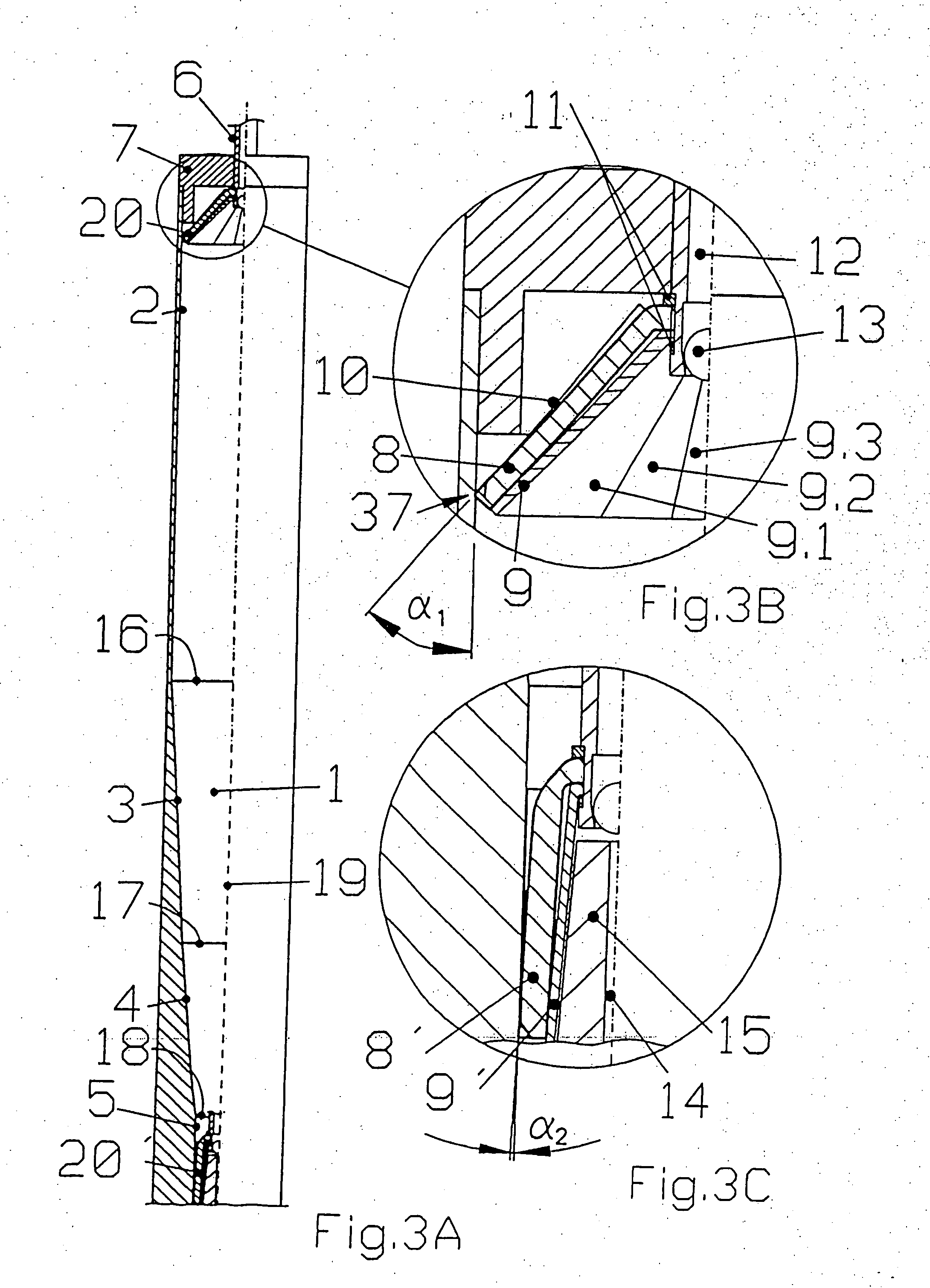
[0073] FIGS. 3A,B,C show details of the The piston moves in the pressurizing chamber which comprises cylindrical and cone-shaped portions with circular transversal cross-sections with diameters that decrease when the pressure of the gaseous and / or liquid media increases. This is based on the specification that the operating force should not exceed a certain maximum. The transition between the various diameters is gradual without discrete steps. This means that the piston can slide easily in the chamber and adapt itself to the changing areas and / or shapes of the transversal cross-sections without loss of sealing ability. If the operating force has to be lowered by increasing pressure, the transversl cross-sectional area of the piston is decreasing and by that the length of the circumference as well. The circumferical length reduction is based on compression up to the buckling level or by relaxation. The longitudinal cross-section of the piston means is trapezoid with variable angle ...

fourth embodiment

[0093] FIGS. 6A,B,C show details of the The piston means comprises a rubber tube which has a reinforcement, e.g. in the form of a textile yard or cord wound around. The neutral angle between the tangent of the reinforcement winding and the centre line of the hose (=so-called braid angle) is mathematically calculated to be 54°44′. A hose under internal pressure will not change dimensions (length, diameter), assuming no elongation of the reinforcement. In this embodiment, the diameter of the piston means decreases in relation to the decreasing diameter of the cross-section of the chamber at increasing pressures. The braid angle should be wider than neutral. The shape of the main part of the longitudinal cross-section of the pressurizing chamber is approximately a cone shape due to the behaviour of the piston means. At the end of the pump stroke, when the compressed medium has been removed from the chamber, the piston means increases its diameter and its length is decreased. The diame...

fifth embodiment

[0101]FIG. 7A,B,C,D,E show details of the pump, with a piston which is constructed as another composite structure, comprising a basic material which is very elastic in all three dimensions, with a very high degree of relaxation. If it is not tight of itself, it can be made tight with e.g. a flexable membrane on the pressurized side of the piston means. The axial stiffness is accomplished by several integrated stiffeners, which in a transversal cross-section lie in a pattern, which optimally fills this section, while the in-between distance is reduced the smaller the diameter of the transversal cross-sectional section is, which in most cases means the higher the pressure in the pressurizing chamber is. In the longitudinal section of the piston the stiffeners lie in several angles between an axial direction and the direction of the surface of the piston means. The higher the pressure rates are, the more these angles are reduced and come near the axial direction. Now therefore the forc...


PUM


Abstract

The object of the invention is to provide a reliable and inexpensive combination of a chamber and a piston to be used in any device where such a combination is needed so that it complies with specific demands towards the operation force for e.g. pumps, specifically manually operated pumps. By a device comprising a chamber and a piston positioned inside the chamber said chamber and said piston relatively movable to each other in a predetermined direction of movement between a first position and a second position of which the cross-section of the chamber in a plane perpendicular to the direction of movement is larger at the first position than at the second position, the change in the cross section of the chamber is essentially continuous between the first position and the second position and the cross-section of the chamber. It is further possible that the piston has a fixed geometrical shape, that the wall of the chamber has different sizes of cross-sections in the direction of the movement and is arranged to adapt itself to the piston. Moreover, both the piston and the wall of the chamber can adapt itself to each other.

Description

TECHNICAL FIELD [0001] This invention concerns a device comprising a combination of a chamber and a piston positioned in the chamber, said chamber and said piston relatively movable to each other in a predetermined direction of movement between a first and a second position. Such combinations can be used in any device where a combination of a chamber and a piston is needed. Examples of these devices are any kind of piston pumps, specifically manually operated piston pumps, actuators, shock absorbers, motors etc. BACKGROUND OF THE INVENTION [0002] A problem with existing manually operated piston pumps is that the arms or leg(s) of the user of the pump are loaded directly. The force that needs to be applied to operate the pump increases with every stroke, if the pressure of a gaseous and / or liquid medium inside a closed body, e.g. a tyre, is to be increased. The force remains the same if the medium is a non-compressable liquid, as e.g. water in water pumps. This gives the user a wrong...

Claims


Application Information

Patent Timeline
Patent Type & Authority Applications(United States)
IPC IPC(8): F16J10/00
CPCF04B33/005F04B39/0005F04B53/143F15B15/1452F16F9/0227F16F9/483F15B15/1428
Inventor BLOM, NICOLAAS VAN DER
Owner VAN DER BLOM NICOLAAS
Learn More