Acoustic transformer and method for transforming sound waves

a technology of acoustic transformer and acoustic wave, which is applied in the direction of transducer casing/cabinet/support, sound producing device, frequency/directions obtaining arrangement, etc., can solve the problems of high undesirable effect of sound and music performance transmission, and achieve the effect of being particularly simple and economical

Inactive Publication Date: 2008-01-10
KLING MARTIN +1
View PDF13 Cites 10 Cited by
  • Summary
  • Abstract
  • Description
  • Claims
  • Application Information

AI Technical Summary

Benefits of technology

[0018] The production becomes particularly simple and economical if, instead of the straight and flat, mutually adjoining walls, the two waveguides have only one common flat dividing wall, which extends from the entrance of the transformer up to its exit and which is covered on either side with a displacement body. This means that the dividing wall, dividing the sound flow of circular cross section into two flows of semicircular cross section, is flat and extends from the entrance of the transformer up to its end and goes over seamlessly into the side walls of the transformer housing.
[0019] Advisably, the displacement body has the shape of a spherical or ellipsoidal cap. Such a displacement body can be produced in very simple molds from plastic, such as a foamed plastic.

Problems solved by technology

Measurements at the rectangular outlet of the above-described acoustic transformer have shown that the latter has resonances for certain frequencies, which is highly undesirable for the transmission of sound and music performances.

Method used


Image

  • Acoustic transformer and method for transforming sound waves
  • Acoustic transformer and method for transforming sound waves
  • Acoustic transformer and method for transforming sound waves

Examples


Embodiment Construction

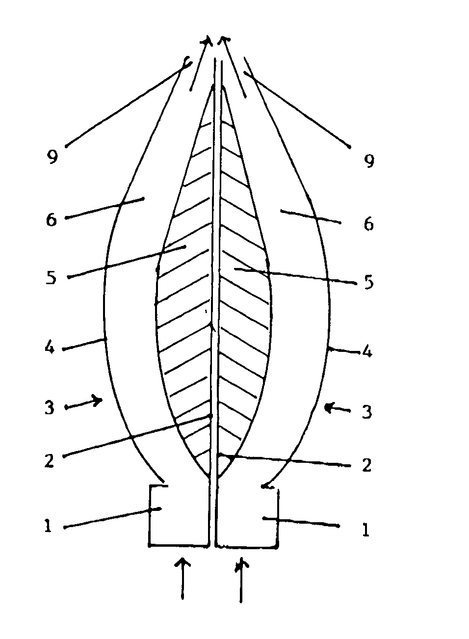
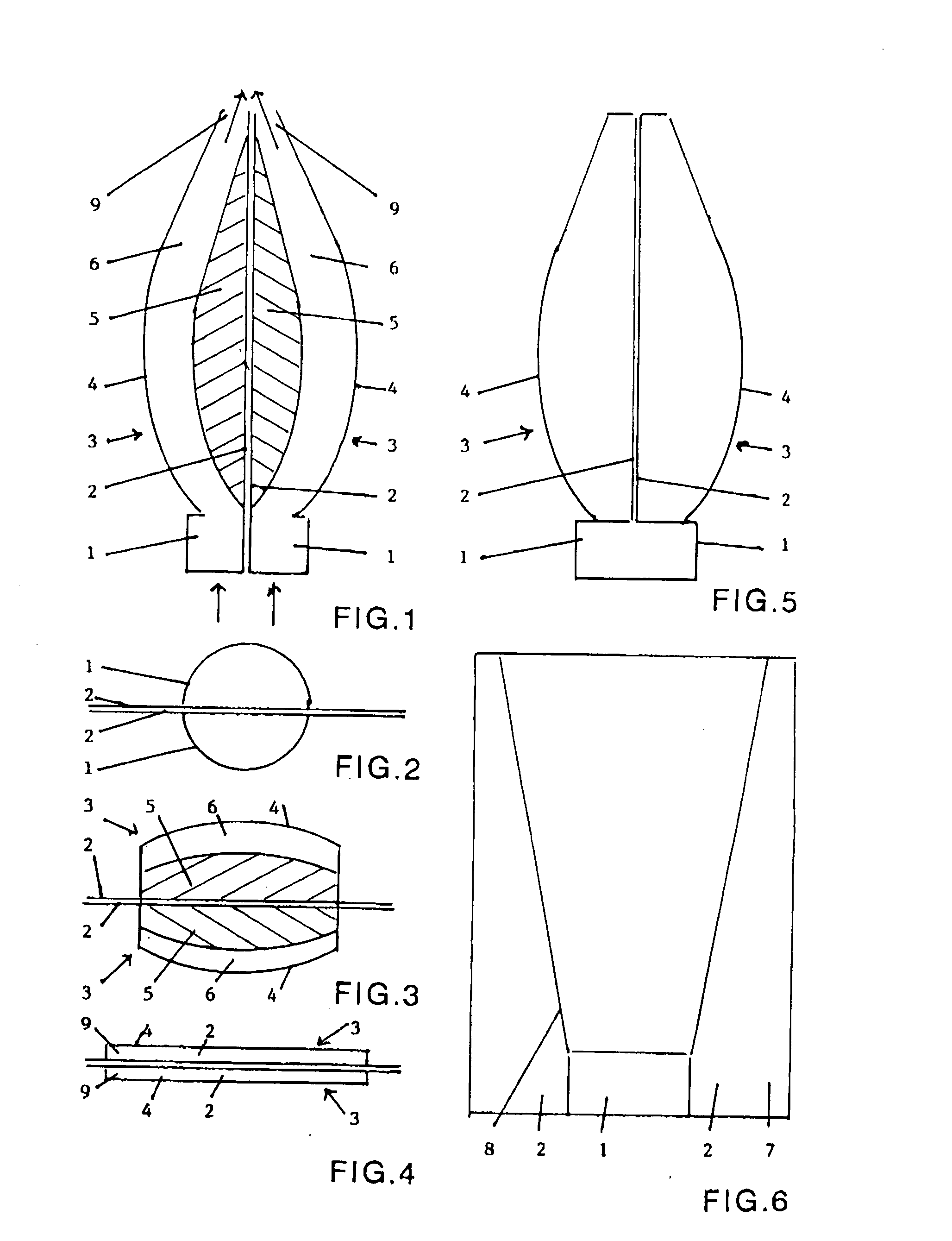
[0035] Referring now to FIGS. 1-6, an acoustic transformer according to an embodiment of the invention is depicted in the various views. In accordance with the embodiment, a generally circular entrance 1 for sound waves is divided in an approximate middle thereof by two dividing walls 2. A pair of waveguides 3 defines a sound path 6 through which the sound waves travel in a direction of the arrows shown in FIG. 1, each of the waveguides 3 being comprised of a corresponding one of the dividing walls 2, a curved outer wall 4, and a displacement body 5 fastened to the inside of each of the corresponding walls 2. The waveguides 3 extend from the generally circular entrance 1 to a generally rectangular exit 9, provided, for example, in the form of a slot, as shown in FIG. 4. The displacement body 5 lengthens the sound path 6 traversed by the sound waves centrally between the entrance 1 to the exit 9. The outer walls 4 of the two waveguides 3 are fastened to dividing walls 2, as shown in ...


PUM


Abstract

An acoustic transformer for transforming sound waves generated by, for example, a round membrane, into a rectangular wave front with reduced interfering resonances is provided in a form of a waveguide with a generally circular entrance and a generally rectangular exit defined by outer walls. The sound waves, arriving from the radiating membrane, are divided geometrically into two flows of sound waves of generally semicircular cross section. Each of the two flows of sound waves is deformed individually into a rectangular shape. Subsequently, the flows of sound waves are brought together once again at an acute angle. The division of the sound flow of circular cross section into two sound flows of semicircular cross section creates two sound flows, which already have a straight side surface. The two sound flows are passed into curved sound guides, which initially have a generally semicircular cross section and then gradually change over into a generally rectangular cross section. A displacement structure which is approximately elliptical in cross section, thickens gradually and, after reaching a maximum, falls off once again, is disposed to protrude inward of the approximately straight and flat wall of each of the sound guides. Each of the displacement structures along with a corresponding one of the outer walls provides a sound channel, which initially is semicircular in cross section, with a bent cross section of uniform thickness and then stretches into a rectangular cross section at an end thereof.

Description

BACKGROUND OF THE INVENTION [0001] The invention relates to an acoustic transformer in the form of a waveguide with a generally circular entrance and rectangular exit, and which includes a fixed wall which, is in the center of the transformer, extends from one side to the other, divides the transformer into two parts of substantially equal size and divides the transformer into two waveguides of substantially identical shape and which have a cross sectional shape, which is initially in the shape of a semicircle and then changes over into the shape of a rectangle. The invention relates further to a method for transforming sound waves radiated by a circular or oval membrane into a rectangularly radiating surface. [0002] Transforming is understood in the present context to be the conversion of a circular sound wave front into a broader rectangular sound wave of identical phase and amplitude, and a transformer is understood herein to be a waveguide which carries out this conversion. [000...

Claims


Application Information

Patent Timeline
Patent Type & Authority Applications(United States)
IPC IPC(8): G10K11/00
CPCH04R1/345G10K11/26
Inventor KLING, MARTIN
Owner KLING MARTIN
Why Eureka
Try Eureka