Multi-force actuator valve with multiple operating modes

a technology of actuator valve and operating mode, which is applied in the direction of operating means/releasing devices of valves, magnets, magnetic bodies, etc., can solve the problems of coils that require high electrical current and power, the actuator valve disclosed in this patent is heavy and bulky, and the limitations of valves and other similar valves, etc., to achieve easy testing, easy service or repair, and easy manufacturing

Inactive Publication Date: 2008-01-10
STANFORD MU CORP
View PDF4 Cites 19 Cited by
  • Summary
  • Abstract
  • Description
  • Claims
  • Application Information

AI Technical Summary

Benefits of technology

[0031] It is an object of the present invention to provide a multi-force actuator valve that is easy to test.
[0032] It is an object of the present invention to provide a multi-force actuator valve that is easy to service or repair.
[0033] It is an object of the invention to provide a multi-force actuator valve that is easy to manufacture.
[0034] It is an object of the invention to provide a multi-force actuator valve that is rugged and reliable.

Problems solved by technology

Unfortunately, this valve and other similar valves have limitations.
However the actuator valve disclosed in this patent becomes heavy and bulky when designed to operate at these higher pressures and flow capacities.
Moreover, the coils require high electrical current and power.
Large weight, size and power are detrimental in aircraft and especially in space flight applications, where weight, size and power must be kept to an absolute minimum.
Another limitation of the actuator valve disclosed in this patent is that it can only be used in “latching valve” applications, e.g., where the valve remains in the last commanded position without electrical power.

Method used


Image

  • Multi-force actuator valve with multiple operating modes
  • Multi-force actuator valve with multiple operating modes
  • Multi-force actuator valve with multiple operating modes

Examples


first embodiment

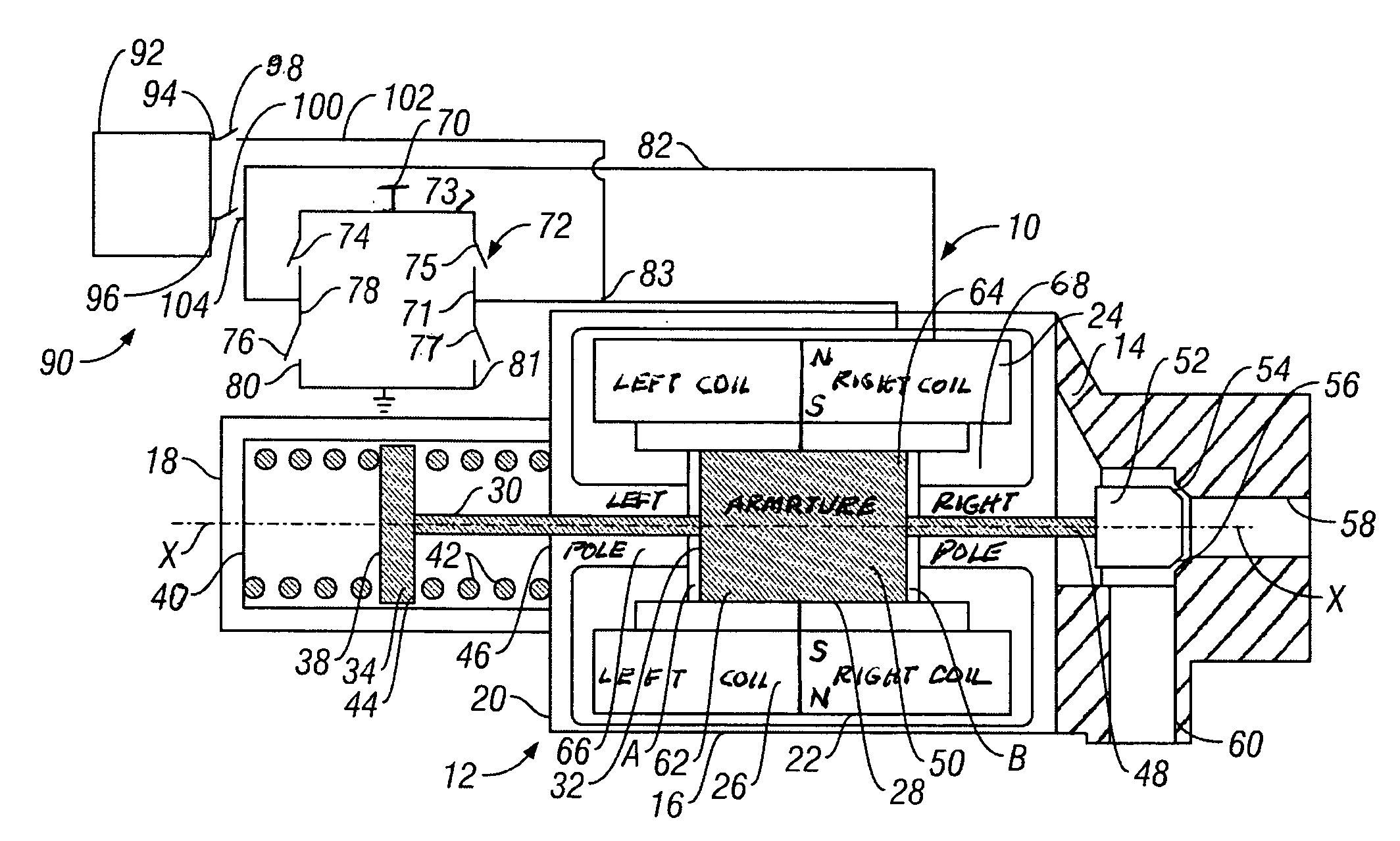
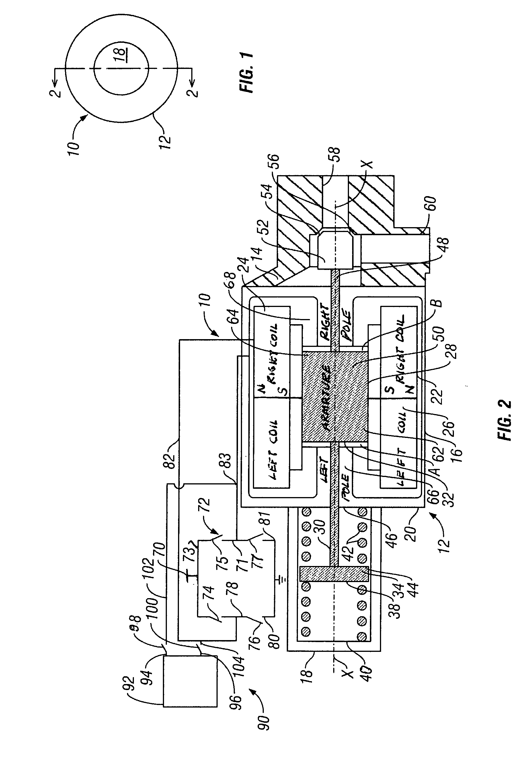
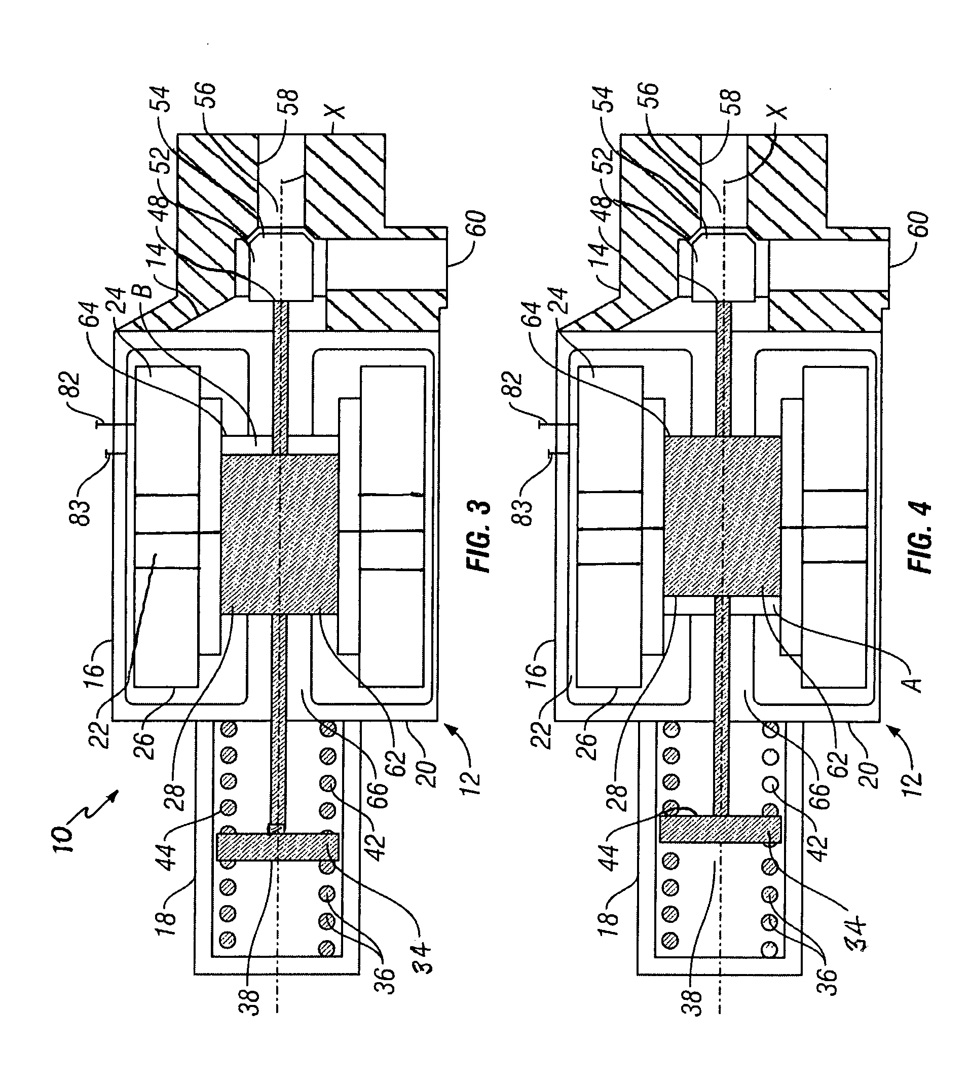
[0043] the multi-force actuator valve is illustrated in FIGS. 1 through 4 and is designated generally by the number 10. It should be understood that the terms left and right used in describing the multi-force activator valve 10 refer to the multi-force activator valve 10 as it is oriented and set forth in FIGS. 2 through 4. The multi-force actuator valve 10 has an actuator housing 12 that is connected to a hollow cylindrical valve housing 14. The actuator housing 12 has a hollow cylindrical main housing 16 and a hollow cylindrical mechanical force housing 18 that is connected to one end 20 of the main housing 16. A donut or toroidal shaped permanent type magnet 22 is centrally located within the main housing 16. In the preferred embodiment, this permanent magnet 22 is a rare earth type permanent magnet. As illustrated, this permanent magnet 22 is radially polarized with the north pole N being located on the outside of the magnet 22 and the south pole S located on the inside of the p...

embodiment 10

[0080] As previously indicated for the multi-force actuator valve embodiment 10, the switches 74, 75, 76, and 77 of the H-bridge circuit 72 and the switches 98 and 100 of the modulating circuit 90 comprise switching means for switching between the plurality of types of controls, including the H-bridge circuit 72 and the modulating circuit 90, for permitting the multi-force actuator valve invention 84 to be switched from one type of valve to another.

[0081] The multi-force actuator valve embodiments 10 and 84 are made for standard materials known in the art using suitable manufacturing and assembly techniques known in the art. The springs 36 and 42 are conventional and the choice of the strength of the spring 36 and 42 or other such mechanical force exerting means will be known to those skilled in the art and will depend on the application for the multi-force actuator valve embodiments 10 and 84. The permanent magnet 22 is conventional and as previously indicated a modern rare-earth p...


PUM


Abstract

A multi-force actuator valve invention including a radially polarized permanent magnet, a pair of associated electromagnetic coils, a movable magnetically operated armature member, a valve located to be actuated by movement of the armature member, and mechanical force exerting means located and positioned to exert a force on the movable magnetically operated armature member. The multi-force actuator valve invention has electrical current control input means for supplying and controlling electrical current to the electromagnetic coils for controlling the movable magnetically operated armature member. The electrical current control input means for supplying and controlling electrical current to the electromagnetic coils for controlling the movable magnetically operated armature member has a plurality of types of controls that allow the multi-force actuator valve invention to operate or function as a plurality of types of valves such as a latching valve or a modulating valve. The electrical current control input means also has switching means for switching between the plurality of types of controls for permitting the multi-force actuator valve invention to be switched from one type of valve to another. In the preferred embodiments the electrical current control input means includes an H-bridge circuit and a modulating circuit.

Description

CROSS-REFERENCE TO RELATED APPLICATIONS [0001] This application claims priority of a prior filed and concurrently pending Provisional Patent Application having Ser. No. 60 / 696,183 and filing date Jul. 7, 2005, and which is incorporated herein by reference.BACKGROUND OF THE INVENTION [0002] Actuator valves are well known and have been in use for many years and have performed in a satisfactory manner. An example of such an actuator valve is set forth in U.S. Pat. No. 3,814,376. This patent describes a linear motion two position valve that utilizes both permanent and electromagnets to provide fast response and low power consumption with magnetic latching in both positions. This is accomplished by utilizing a linear motion armature that also serves as the movable valve member, providing a permanent magnet to latch the armature in either valve open or valve closed position, and using a pair of like wound solenoid coils for moving the armature from one position to the other. The coils are...

Claims


Application Information

Patent Timeline
Patent Type & Authority Applications(United States)
IPC IPC(8): F16K31/08
CPCF16K31/082H01F2007/1692H01F7/1615
Inventor REINICKE, ROBERT H.
Owner STANFORD MU CORP
Why Eureka
Try Eureka