Pantagraph-type jack

a jack and pentagon technology, applied in the direction of lifting devices, etc., can solve the problem that much consideration is not given to inward falling

Inactive Publication Date: 2008-01-10
RIKEN KAKI KOGYO CO LTD
View PDF4 Cites 4 Cited by
  • Summary
  • Abstract
  • Description
  • Claims
  • Application Information

AI Technical Summary

Benefits of technology

[0007] The present invention has been achieved in view of the above-mentioned circumstances, and it is an object of the present invention to provide a pantagraph-type jack in which inward falling of side plate portions of lower arms and upper arms in the vicinity of lower pivots and upper pivots is firmly restricted by a reinforcement structure, and a load bearing platform can be lowered to a lowermost position without interference by the reinforcement structure.
[0009] With the first feature, at the inner end of each side plate portion of the lower arms and the upper arms, the inner side surface abuts on the end surface of the flange portion, having a high buckling strength, of the lower and upper reinforcement plates, whereby the inward falling of the side plate portion is firmly restricted to improve durability of the side plate portion. Further, when the load bearing platform is lowered to the lowermost position, parts of the threaded rod is received in the recesses of the flange portion, and thus the jack can be compactly folded without interference by the lower and upper reinforce plates. Furthermore, even if the outer peripheral surface of the threaded rod abuts on the inner surfaces of the recesses of the flange portions, there is no fear that the abutment damages the threaded portion of the threaded rod, because areas of the inner surfaces of the recesses of the flanges are relatively large.
[0011] With the second feature, when the flanges, having a high rigidity, of the upper and lower reinforcement plates abut on the inner side surfaces of the side plate portions of the lower arms and the upper surfaces, they also abut on the inner side surfaces of the lower and upper sector gears having a high rigidity, thereby further firmly restricting the inward falling of the side plate portions of the lower arms.

Problems solved by technology

However, much consideration is not given to inward falling thereof.

Method used


Image

  • Pantagraph-type jack
  • Pantagraph-type jack
  • Pantagraph-type jack

Examples


Embodiment Construction

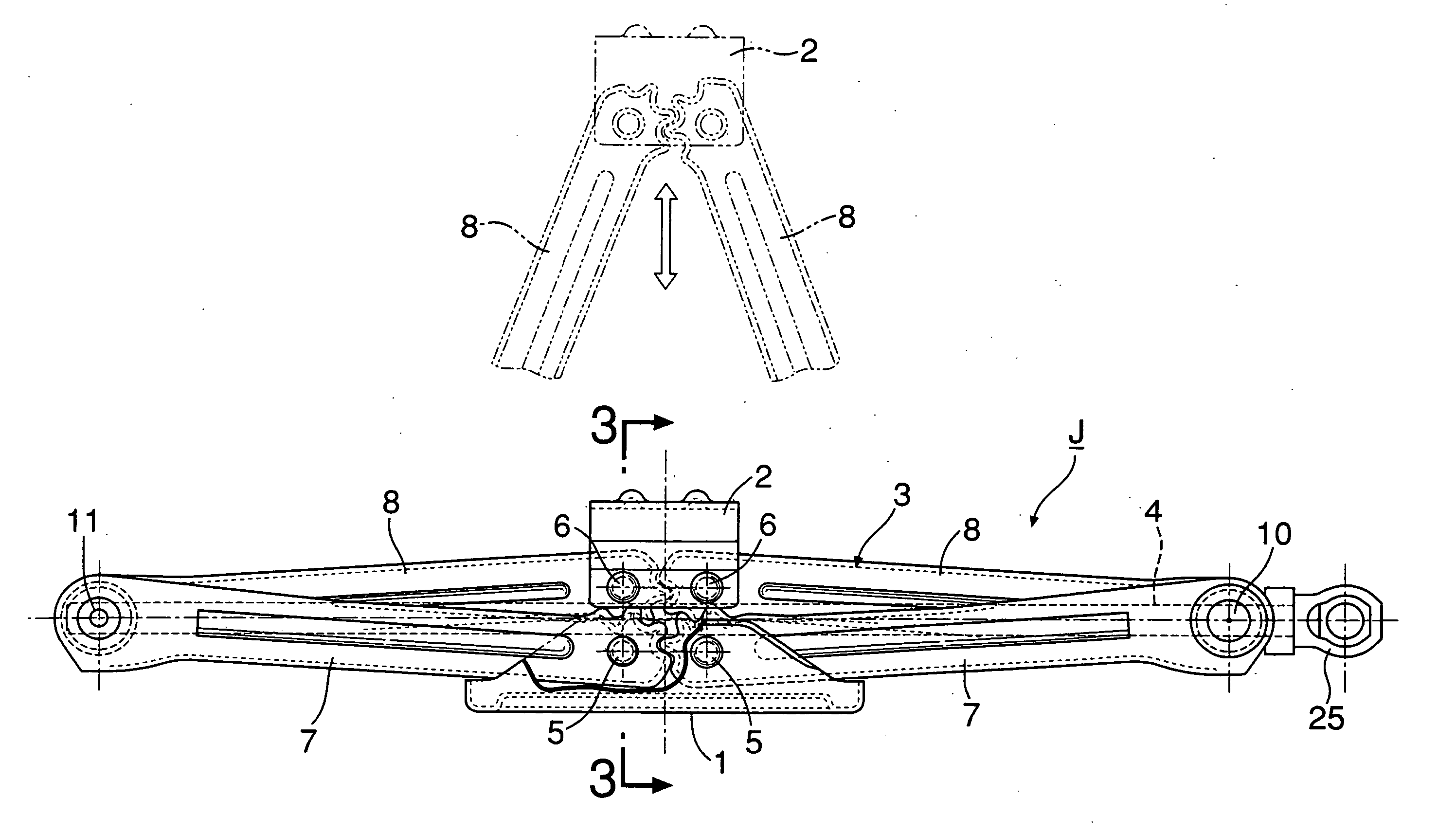
[0019] First, in FIGS. 1 and 2, a jack J is a so-called pantagraph-type having four link arms connected in a pantagraphic manner. The jack J includes a base 1, a load bearing platform 2 arranged directly on the base 1, a link mechanism 3 which connects the base 1 and the load bearing platform 2 to each other, and a threaded rod 4 for raising and lowering the load bearing platform 2 by driving the link mechanism 3.

[0020] As shown in FIGS. 1 to 3, the base 1 is one steel plate bent into an angular U-shape, and comprises: a pair of side plate portions 1a and 1a opposed to each other in the front-rear direction, that is, in a width direction of the Jack J; and a bottom plate portion 1b integrally connecting the lower ends of the side plate portions 1a and 1a to each other. The bottom plate 1b is integrally formed with ground legs 1c and 1c protruding in the front-rear direction from opposite left and right ends of the bottom plate 1b.

[0021] The load bearing platform 2 is one steel pla...


PUM


Abstract

In a pantagraph-type jack, a lower reinforcement plate is integrally provided at an inner end of a bottom plate portion of each lower arm so as to extend therefrom in parallel with a corresponding lower pivot, and a lower recess is formed in an upper surface of a flange portion of each lower enforcement plate so that the lower recess receives a part of an outer peripheral surface of a threaded rod when a load bearing platform is lowered to a lowermost position. Also, an upper reinforcement plate having the same structure is integrally provided at an inner end of an upper plate portion of each upper arm. Thus, it is possible to firmly restrict inward falling of side plate portions of the lower arms and upper arms, and to lower the load bearing platform to a lowermost position without interference by the above-described reinforcement structure.

Description

CROSS-REFERENCE TO RELATED APPLICATIONS [0001] The present invention claims priority under 35 USC 119 based on Japanese patent application No. 2006-189419, filed on Jul. 10, 2006. The entirety of the subject matter of this priority document is incorporated by reference herein. BACKGROUND OF THE INVENTION [0002]1. Field of the Invention [0003] The present invention relates to a pantagraph-type jack, particularly to an improvement of a pantagraph-type jack comprising: a base; a load bearing platform; a pair of right and left lower arms arranged into a V-shape, formed into an upwardly-opened angular U-shape in section, and having inner ends swingably connected through a pair of right and left lower pivots to the base; a pair of right and left upper arms arranged into an inverted V-shape, formed into a downwardly-opened angular U-shape in section, and having inner ends swingably connected through a pair of right and left upper pivots to the load bearing platform; outer ends of the right...

Claims


Application Information

Patent Timeline
Patent Type & AuthorityApplications(United States)
IPC IPC(8): B66F3/00
CPCB66F3/12
InventorKIKUCHI, NORIYUKI
OwnerRIKEN KAKI KOGYO CO LTD