Switching power supply, electronic apparatus, and method of controlling switching power supply circuit

a technology of switching power supply and electronic equipment, which is applied in the direction of power conversion systems, dc-dc conversion, instruments, etc., can solve the problems of limiting the effectiveness of reducing the required standby power, certain amount of power consumption, and complicated circuit configuration of controlling the switching element, etc., to achieve simple circuit configuration, reduce the effect of power consumption and reduce the effect of standby power

Inactive Publication Date: 2008-01-10
SONY CORP
View PDF4 Cites 141 Cited by
  • Summary
  • Abstract
  • Description
  • Claims
  • Application Information

AI Technical Summary

Benefits of technology

[0009] It has been required, particularly in recent years, to reduce the standby power as a measure of achieving low power consumption of an electronic apparatus, and in order for reducing the standby power consumed while the apparatus is in the standby state, it is required to reduce the power consumption of the switching power supply device in the standby state. However, in reality, in order for generating the PWM wave with variable duty cycle, certain level of circuit configuration is required, which causes a certain amount of power consumption, and problematically limits the effectiveness of reducing the required standby power.
[0011] In view of the above points, it may be desirable to provide a switching power supply circuit simple in the circuit configuration and superior in the conversion efficiency.
[0014] According to an embodiment of the invention, by providing the circuit for generating the square wave with a constant duty cycle, an output with desired voltage range can be obtained, and the switching power supply can be configured with a very simple circuit configuration. Further, the circuit configuration is simple, and the conversion efficiency is high, therefore, low power consumption of the apparatus provided with the switching power supply can be achieved.

Problems solved by technology

Incidentally, since the switching power supply device in the related art has the configuration of obtaining a desired output voltage by changing the duty cycle of the PWM wave for controlling the switching element, it is required to generate the PWM wave with variable duty cycle, and accordingly, the configuration of controlling the switching element has been problematically complicated.
However, in reality, in order for generating the PWM wave with variable duty cycle, certain level of circuit configuration is required, which causes a certain amount of power consumption, and problematically limits the effectiveness of reducing the required standby power.
Although in the patent document described above, there is described the configuration of reducing the power consumption by temporarily switching off the circuit for generating the variable PWM wave, there has been a limitation in the improvement of power consumption (the conversion efficiency) in the switching power supply device as long as the circuit for generating the variable PWM wave is employed.

Method used


Image

  • Switching power supply, electronic apparatus, and method of controlling switching power supply circuit
  • Switching power supply, electronic apparatus, and method of controlling switching power supply circuit
  • Switching power supply, electronic apparatus, and method of controlling switching power supply circuit

Examples


Embodiment Construction

[0023] Hereinafter, the first embodiment of the invention will be explained with reference to FIGS. 1 through 4.

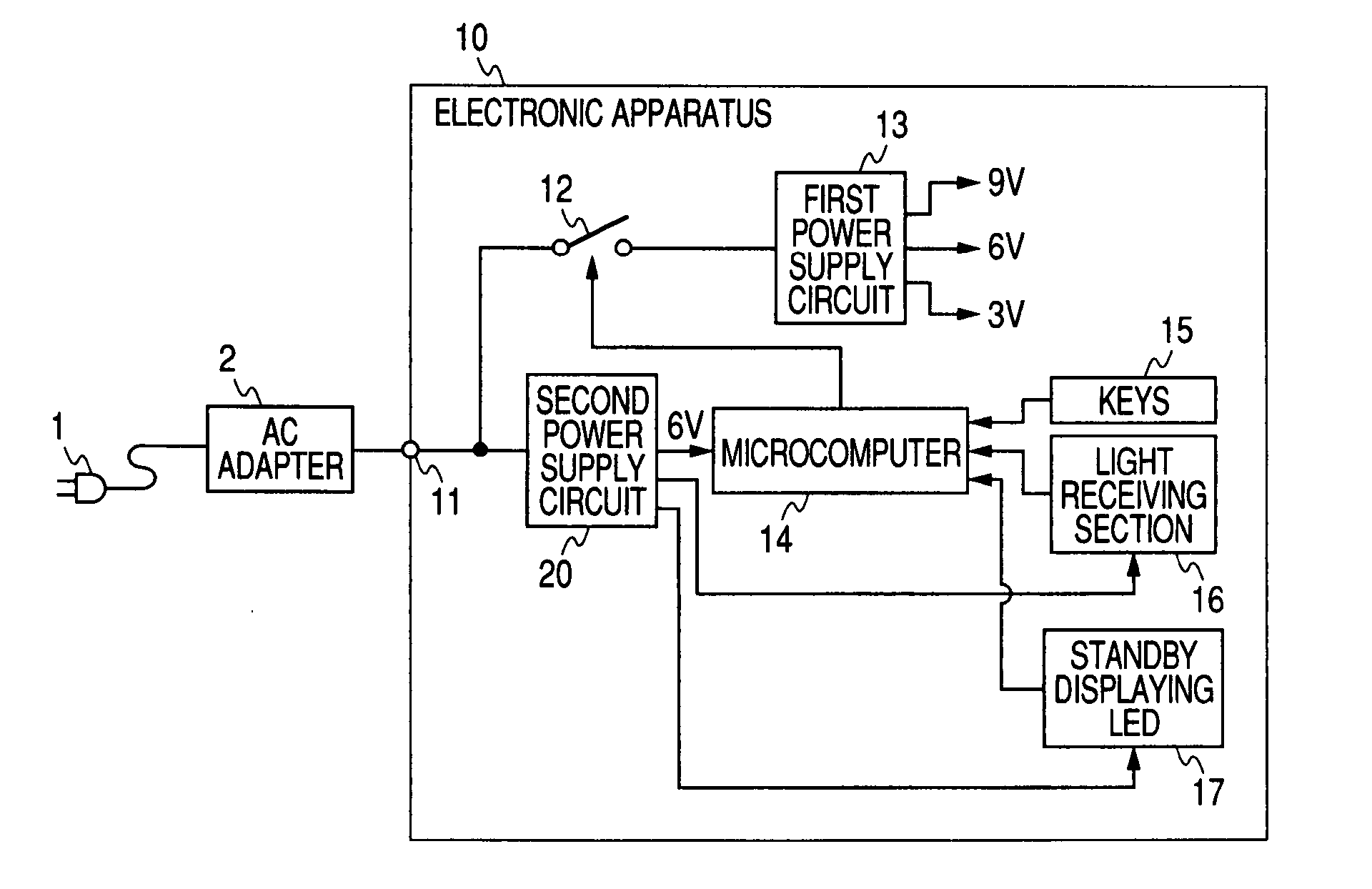
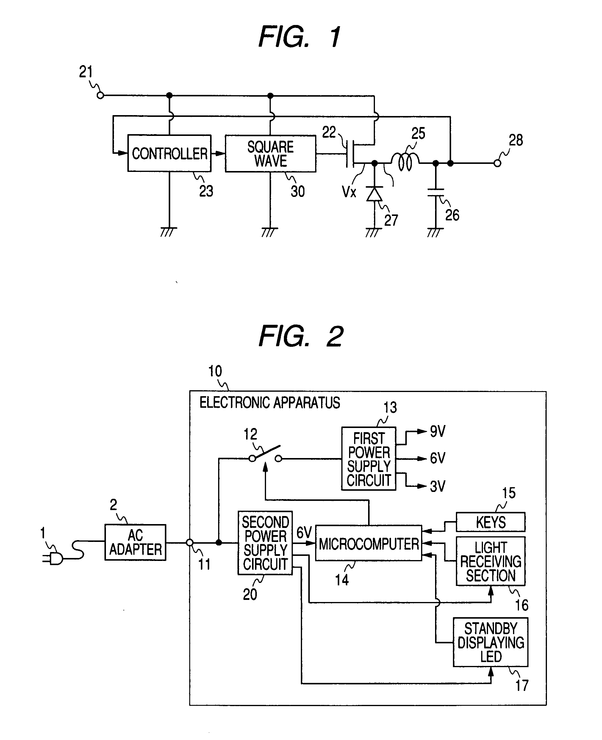
[0024] In the present embodiment, it is applied to a power supply circuit (a power supply device) required for an electronic apparatus. The electronic apparatus is provided with two power supply circuits, namely a power supply circuit for supplying necessary power in the power-on state and a power supply circuit for supplying power to the circuit to be always operated in the standby state when powered-off.

[0025] Firstly, the power supply configuration of the electronic apparatus will be explained with reference to FIG. 2. The electronic apparatus 10 is provided with a direct-current power input terminal 11. The direct-current power input terminal 11 is arranged to be variable voltage active input accepting low voltage direct-current power supply in a predetermined range such as 8V through 12V. Although there is adopted a configuration in which the direct-current power in...


PUM


Abstract

A switching power supply device may include a switching element for switching an input direct-current power, a smoothing section for smoothing and then outputting the direct-current power switched by the switching element, a square wave generating section for generating a square wave with a constant duty cycle to control switching by the switching element, and a control section for watching an output voltage of the smoothing section to control a period of generating the square wave generated by the square wave generating section so that the output voltage may be organized within a certain range.

Description

CROSS-REFERENCE TO RELATED APPLICATIONS [0001] This application claims priority from Japanese Patent Application No. JP 2006-139461 filed in the Japanese Patent Office on May 18, 2006, the entire content of which is incorporated herein by reference. BACKGROUND OF THE INVENTION [0002] 1. Technical Field [0003] The present invention relates to a switching power supply device for converting the voltage of a direct-current power supply, an electronic apparatus equipped with the power supply device, and a method of controlling the switching power supply circuit applied to control of the power supply device. [0004] 2. Related Art [0005] From the past, the switching power supply devices have widely been used as the power supply circuits (devices) of various electronic apparatuses. In the configuration of a typical switching power supply device in related art, there is provided a switching element for switching the input power supply at high speed, and the output power supply is obtained by...

Claims


Application Information

Patent Timeline
Patent Type & Authority Applications(United States)
IPC IPC(8): G05F1/10H02M7/00
CPCH02M3/156H02M3/155G05F1/10
Inventor NAGASHIMA, TAKAYUKINAKAMURA, SHINJIHIRASE, AKIHIRO
Owner SONY CORP
Why Eureka
Try Eureka