
Image-forming apparatus, image-forming method, and recording medium

Active Publication Date: 2008-01-10
FUJIFILM BUSINESS INNOVATION CORP
View PDF3 Cites 32 Cited by
  • Summary
  • Abstract
  • Description
  • Claims
  • Application Information

AI Technical Summary

Benefits of technology

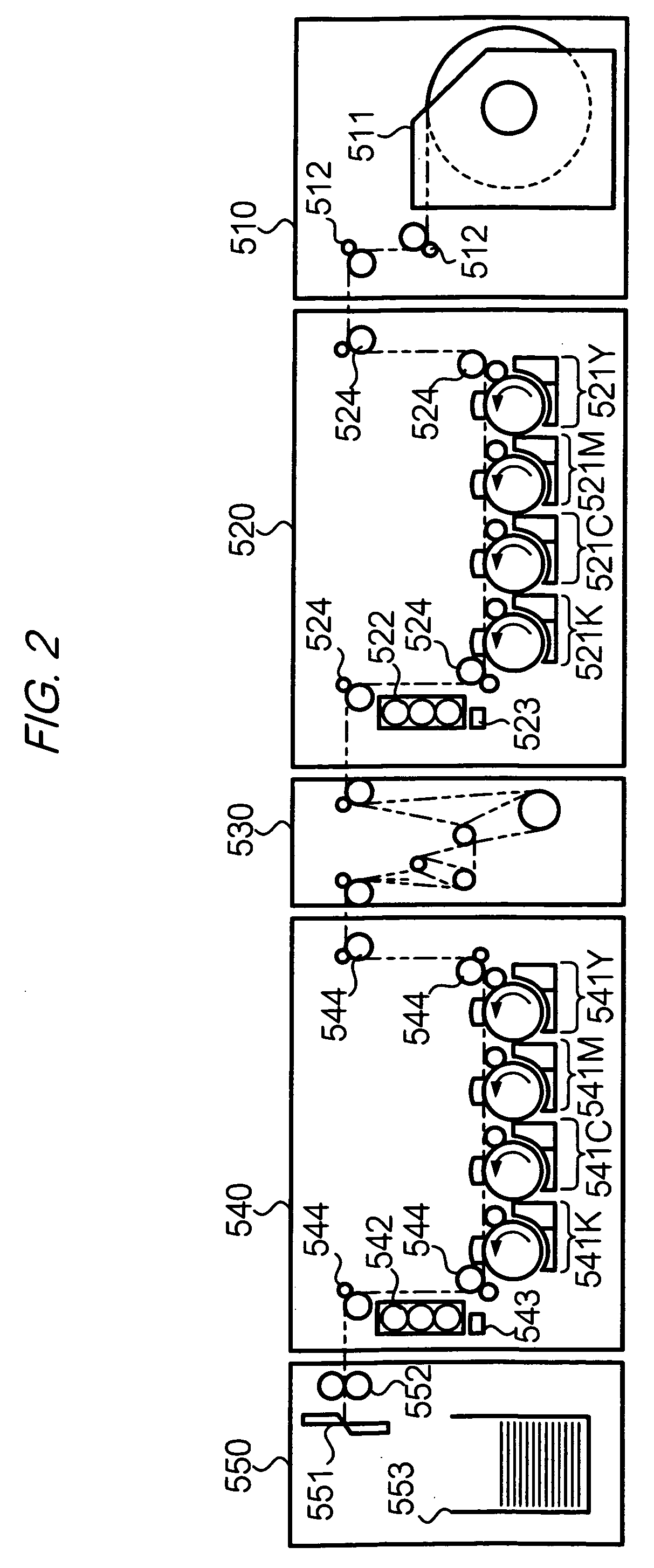
[0006]In the image-forming apparatus having the structure described above, eight image-forming units and a front/back reversing device are provided in series. This arrangement causes a distance over which a sheet is required to be conveyed, to be lengthened. As a result, a conveyed sheet is liable to move in an unstable manner at a start of conveyance due to structural and mechanical factors. Instability at the start of conveyance gives rise to a meander movement in the conveyed sheet. When meander occurs at a time that an image-forming apparatus according to the tandem scheme is forming an image, positions of toner images of respective colors become displaced in relation to one another, and color drift occurs. To form images using such an apparatus which is not prone to color drift, it is necessary to delay a start of image formation for a certain period following start of conveyance of a sheet, so as to allow meander of the sheet to stabilize. Thus, to ensure that an image is formed without color drift, a sheet on which the image is to be formed is subject to a “preparatory period” during which the sheet is conveyed without any image formation operation being carried out. However, use of such a preparatory operation can result in a loss of as much as 200 meters of sheet. Moreover, sin

Problems solved by technology

As a result, a conveyed sheet is liable to move in an unstable manner at a start of conveyance due to structural and mechanical factors.
However, use of such a preparatory operation can result in a loss of as much as 200 meters of sheet.
Moreover, since image formation does not take place during the preparatory operation, a significant amount of image-formation time is lost, and a relatively long time is thereby required to complete an image-forming operation.

Method used


Image

  • Image-forming apparatus, image-forming method, and recording medium
  • Image-forming apparatus, image-forming method, and recording medium
  • Image-forming apparatus, image-forming method, and recording medium

Examples


operation example 1

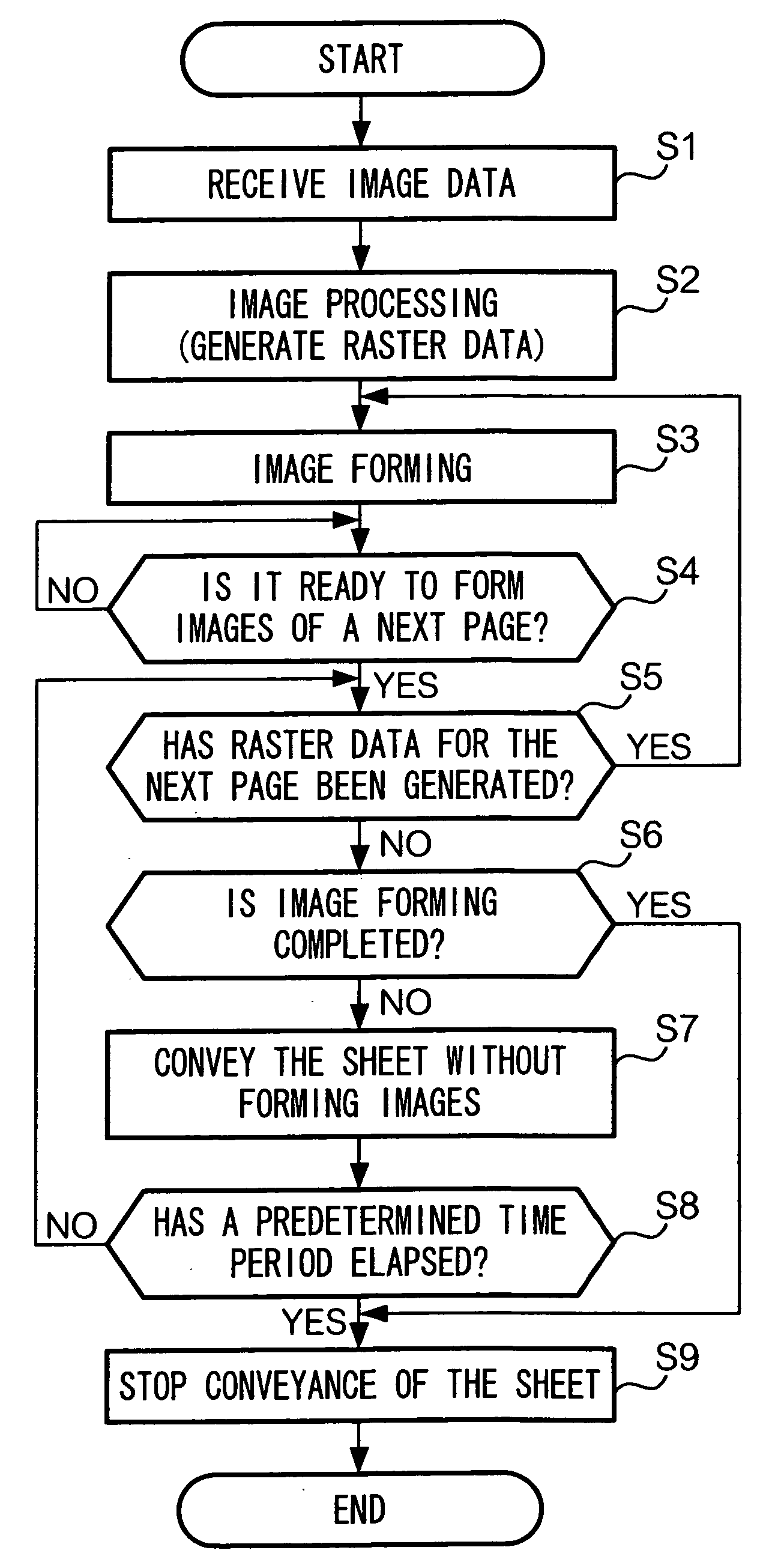
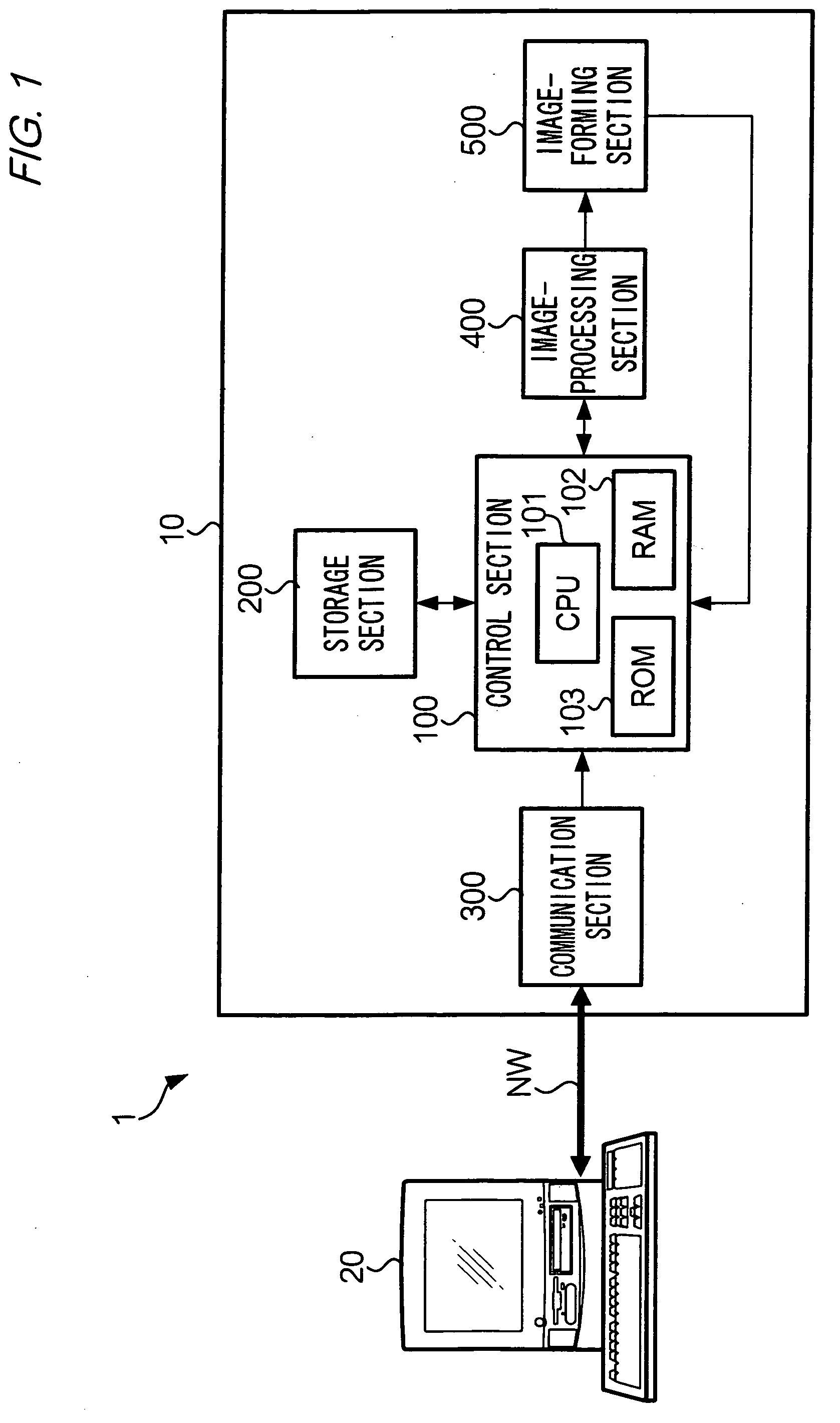
[0023]FIG. 3 is a flowchart showing the first operation example. A description will be made of the processes shown in the flowchart. The control section 100 of the image-forming apparatus 10 first receives image data from the host apparatus 20 (step S1). Subsequently, the control section 100 supplies the image-processing section 400 with the received image data, so that the section 400 is made to execute an image processing such as a rasterizing processing to generate raster data for each of the colors Y, M, C, and K. The raster data includes a part corresponding to front surface image data, and a part corresponding to back surface image data.

[0024]After the necessary raster data is generated, the control section 100 supplies the raster data to the image-forming section 500 and causes the section 500 to form images according to the raster data (step S3). At this time, the image-forming section 500 forms an image corresponding to the front surface image data. The front / back reversing...

operation example 2

[0032]The second operation example will be described next. This operation example is a partial modification of the first operation example and follows operations in the same manner as shown in the flowchart of FIG. 3. Therefore, the following description will be mainly directed to differences in the second operation example, and overlapping description will be omitted.

[0033]FIG. 4 is a flowchart showing the second operation example of the image-forming apparatus 10. In this figure, those steps that execute the same processing as shown in the flowchart of FIG. 3 are denoted by the same reference symbols. That is, operation of the image-forming apparatus 10 in the present example differs from the first operation example mainly with respect to processing that is executed while waiting for raster data of a next page.

[0034]In the present operation example, if raster data corresponding to a next page has not yet been generated, the control section 100 of the image-forming apparatus 10 all...


PUM


Abstract

An image-forming apparatus includes: a supply section that supplies image data; an image-forming section that forms on a continuous sheet a toner image according to the image data; a conveyor section that conveys the continuous sheet; and a control section that controls operations of the conveyor section and the image-forming section. If a first toner image according to first image data and a second toner image according to second image data are formed on the continuous sheet, the control section controls conveyance of the continuous sheet so as not to be halted until the second toner image is formed if the second image data is supplied before a predetermined time period elapses from when the first toner image is formed, or so as to be stopped if the second image data is not supplied before the predetermined time period elapses from when the first toner image is formed.

Description

BACKGROUND OF THE INVENTION[0001]1. Field of the Invention[0002]The present invention relates to an image-forming apparatus and an image-forming method according to an electrophotographic process used for creating printed material such as newspapers, and also to a recording medium used for the apparatus and method.[0003]2. Description of the Related Art[0004]Conventionally, printed materials for publication, such as newspapers, are produced using printing machines. However, it has become increasingly common for electrophotographic image-forming apparatuses to be used in place of printing machines for producing printed materials. An advantage of using such an apparatus is that it is not necessary to prepare a block copy set. Accordingly, an electrophotographic image-forming process is particularly suited for use in producing small job lots of printed materials.[0005]In an image-forming apparatus for use in an electrophotographic process it is preferable to employ a so-called tandem s...

Claims


Application Information

Patent Timeline
IPC IPC(8): H04N1/04
CPCH04N1/0057H04N1/00588H04N1/00591H04N2201/0082H04N1/00649H04N1/00665H04N1/00676H04N1/00602
Inventor YAMAMOTO, YOSHIKAZU
Owner FUJIFILM BUSINESS INNOVATION CORP
Learn More