Image forming apparatus, method of recommending replacement of rotatable member, method of cleaning rotatable member and method of controlling image formation

a technology of image forming apparatus and rotatable member, which is applied in the direction of electrographic process apparatus, instruments, optics, etc., can solve problems such as deformation of images

Inactive Publication Date: 2008-01-10
FUJIFILM BUSINESS INNOVATION CORP
View PDF1 Cites 10 Cited by
  • Summary
  • Abstract
  • Description
  • Claims
  • Application Information

AI Technical Summary

Benefits of technology

[0009]According to an aspect of the present invention, an image forming apparatus includes: an imaging device that forms a toner image based on image data and transfers the toner image to a recording medium; a fixing device including a pair of rotatable members that defines a contact pressing portion that allows the recording medium with the toner image to pass through, and heats and presses the recording medium with the toner image

Problems solved by technology

This poses problems such as a stain on a sheet and a blur

Method used


Image

  • Image forming apparatus, method of recommending replacement of rotatable member, method of cleaning rotatable member and method of controlling image formation
  • Image forming apparatus, method of recommending replacement of rotatable member, method of cleaning rotatable member and method of controlling image formation
  • Image forming apparatus, method of recommending replacement of rotatable member, method of cleaning rotatable member and method of controlling image formation

Examples


first exemplary embodiment

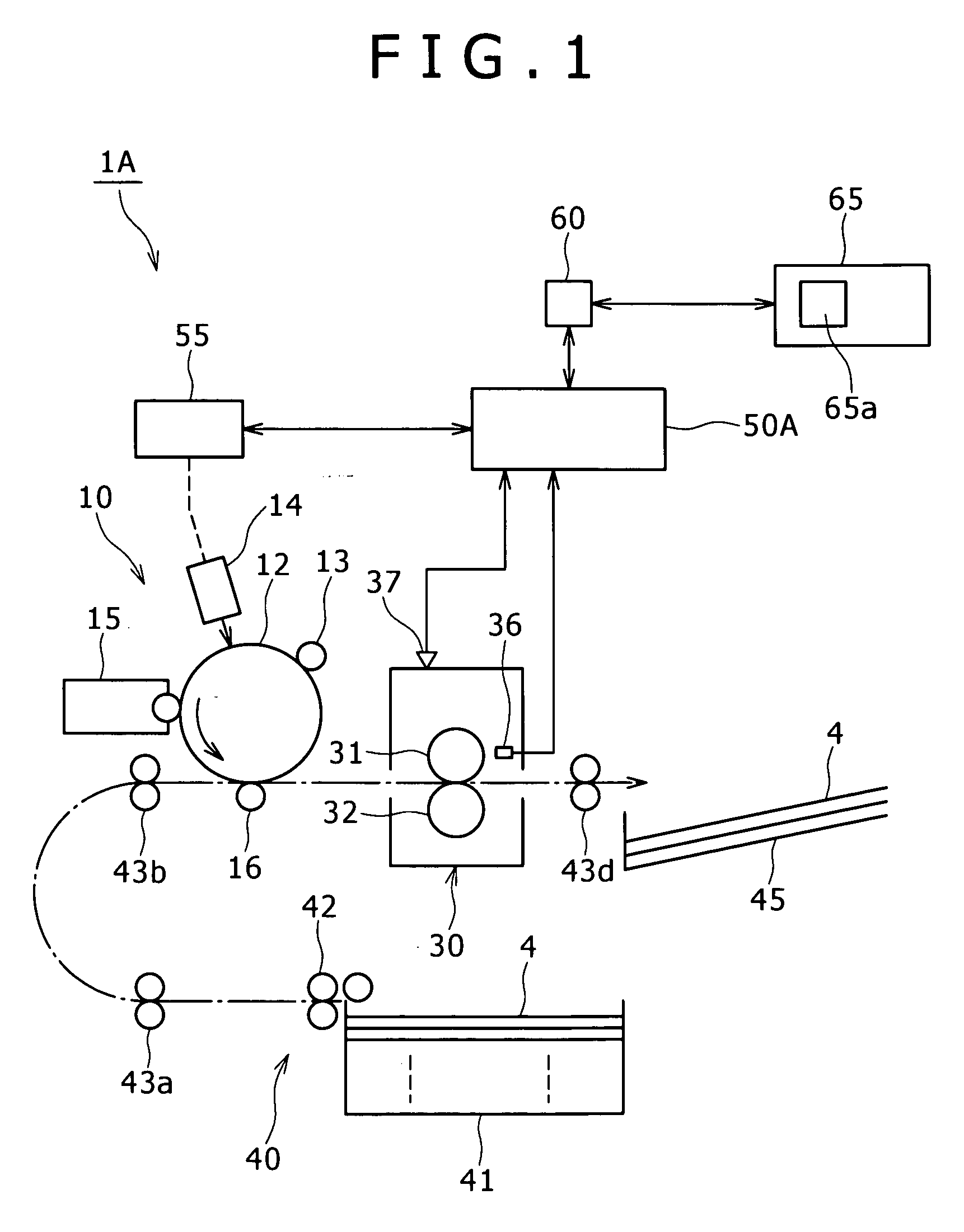
[0024]FIG. 1 shows an overview of an image forming apparatus relevant to a first exemplary embodiment of the present invention.

[0025]This image forming apparatus 1A is configured as a printer, for example, and, inside its mainframe which is not shown, the apparatus is primarily equipped with an imaging device 10 which forms a toner image based on image data and transfers the toner image to a sheet 4 of paper, a fixing device 30 which thermally fixes the toner image transferred to the sheet 4 guided to pass through it, and a paper feeding device 40 which feeds the sheet 4 to the imaging device 10, and a controller 50A which is responsible for overall control for an image forming operation by the imaging device 10, the fixing device 30, the paper feeding device 40, and other components. In FIG. 1 and a related description, reference numeral 65a denotes a display such as a liquid crystal panel and a chain line with an arrow indicates a transport path of the sheet 4.

[0026]In this image ...

second exemplary embodiment

[0057]FIG. 6 shows an overview of an image forming apparatus relevant to a second exemplary embodiment of the present invention.

[0058]This image forming apparatus 1B is made up of the same components as those of the image forming apparatus 1A relevant to the first exemplary embodiment, except that a controller 50B is applied; a part of its control operation for preventing toner offset differs. Thus, the components corresponding to those of the image forming apparatus 1A relevant to the first exemplary embodiment are assigned the same reference numerals in FIG. 6 and a related description and their explanation will not be repeated in the following, unless necessary.

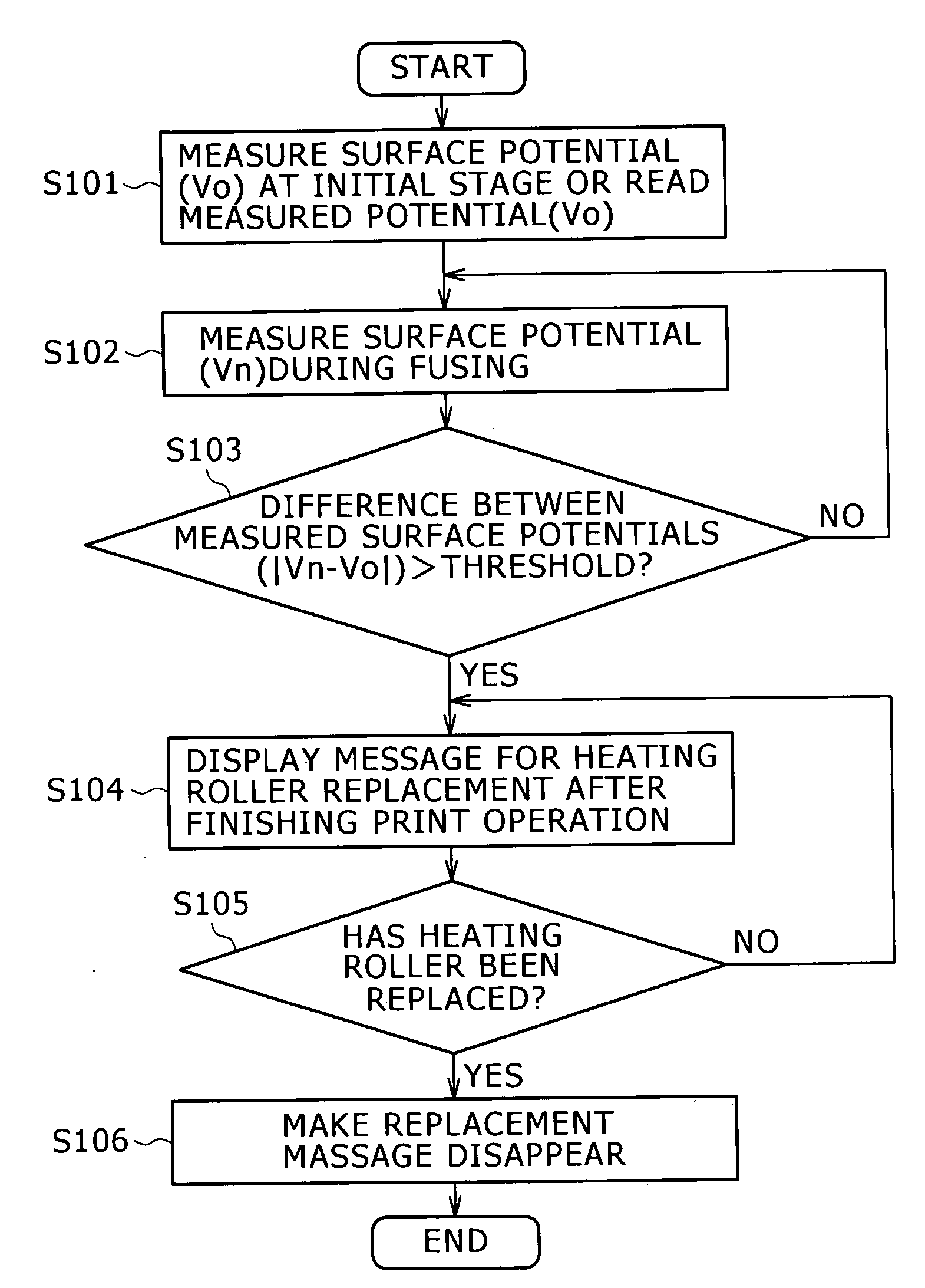
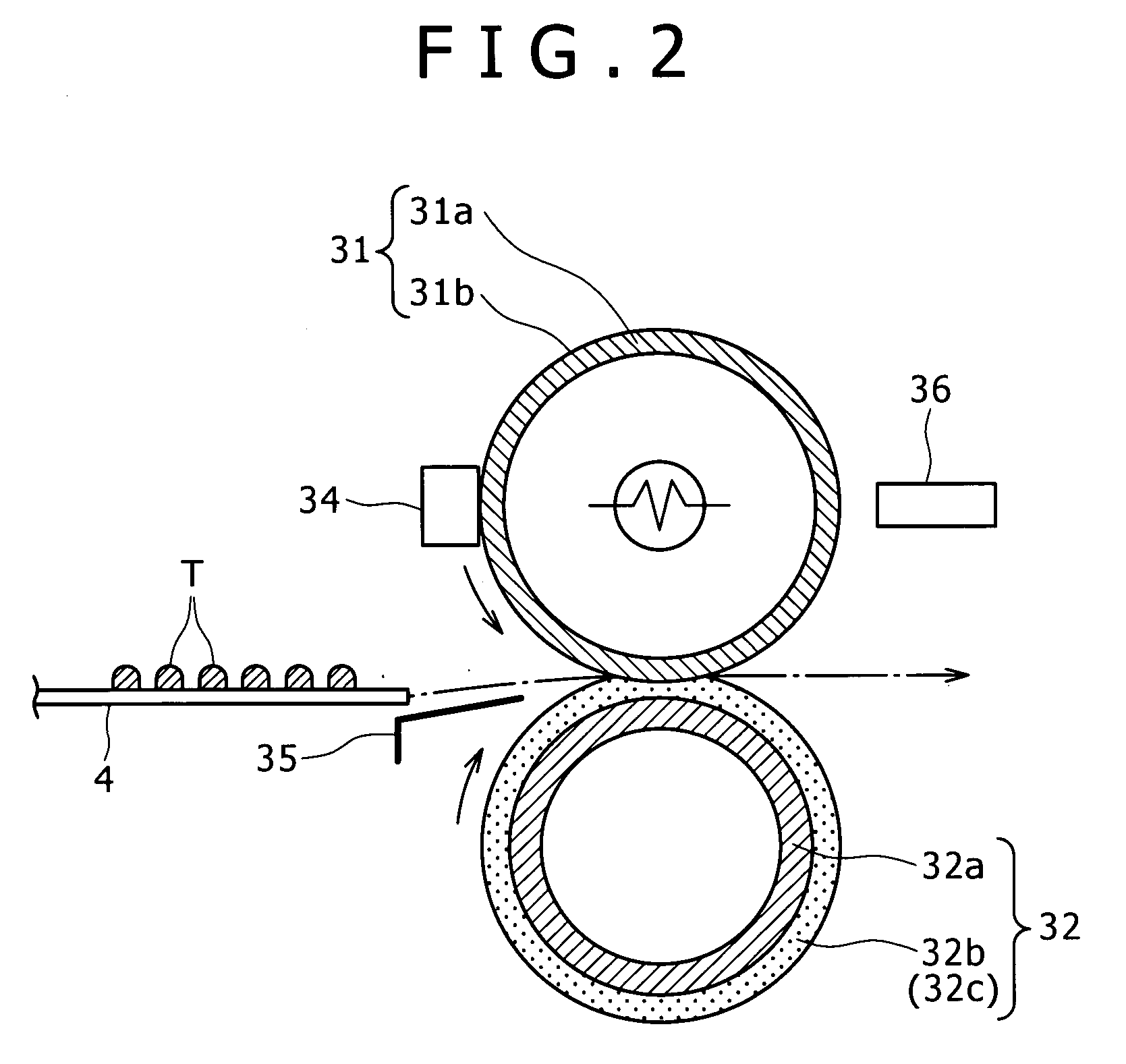
[0059]The controller 50B in the second exemplary embodiment is adapted to carry out the control operation for preventing toner offset as illustrated in FIG. 7, according to the result of detection made by the surface potential measuring device 36 which measures the surface potential of the heating roller 31 of the fixing d...

third exemplary embodiment

[0070]FIG. 10 shows an overview of an image forming apparatus relevant to a third exemplary embodiment of the present invention.

[0071]This image forming apparatus 1C is made up of the same components as those of the image forming apparatus 1A relevant to the first exemplary embodiment, except that a controller 50V is applied; a part of its control operation for preventing toner offset differs. Thus, the components corresponding to those of the image forming apparatus 1A relevant to the first exemplary embodiment are assigned the same reference numerals in FIG. 10 and a related description and their explanation will not be repeated in the following, unless necessary.

[0072]The controller 50C in the third exemplary embodiment is adapted to carry out the control operation for preventing toner offset as illustrated in FIG. 11, according to the result of detection made by the surface potential measuring device 36 which measures the surface potential of the heating roller 31 of the fixing ...


PUM


Abstract

An image forming apparatus includes: an imaging device that forms a toner image based on image data and transfers the toner image to a recording medium; a fixing device including a pair of rotatable members that defines a contact pressing portion that allows the recording medium with the toner image to pass through, and heats and presses the recording medium with the toner image; a surface potential measuring device that measures a surface potential of at least one of the pair of rotatable members; and a controller that performs control to give an alert notification that at least one of the pair of rotatable members which contacts with the toner image to be fixed should be replaced, when a result of the surface potential measured by the surface potential measuring device has exceeded a predetermined value.

Description

CROSS-REFERENCE TO RELATED APPLICATIONS[0001]This application is based on and claims priority under 35 USC 119 from Japanese Patent Application No. 2006-187473 filed Jul. 7, 2006.BACKGROUND[0002]1. Technical Field[0003]The present invention relates to image forming apparatus that forms an image with dry toner (developing powders), such as printers, copiers, facsimiles, and hybrid machines as well as a method of recommending replacement of a rotatable member, a method of cleaning a rotatable member, and a method of controlling image formation. Particularly, the invention relates to an image forming apparatus provided with a new function for preventing toner offset from occurring in a fusing device that fuses and fixes a toner image transferred onto a sheet of paper as well as a method of recommending replacement of a rotatable member, a method of cleaning a rotatable member, and a method of controlling image formation.[0004]2. Related Art[0005]An image forming apparatus such as print...

Claims


Application Information

Patent Timeline
IPC IPC(8): G03G15/20
CPCG03G15/553G03G15/2064
Inventor KURITA, ATSUMIYAMADA, TETSUOINOUE, TOHRUKAKISHIMA, AYA
Owner FUJIFILM BUSINESS INNOVATION CORP
Why Eureka
Try Eureka