
Developing device and image-forming apparatus

Active Publication Date: 2009-12-17
KYOCERA DOCUMENT SOLUTIONS INC
View PDF3 Cites 9 Cited by
  • Summary
  • Abstract
  • Description
  • Claims
  • Application Information

AI Technical Summary

Benefits of technology

[0009]According to one embodiment of the present invention a developing device may comprise a developing roller that has improved toner releasability and solves the problem of electric charge accumulation in the resin layer caused by inferior dispersion of a conductive material within the resin layer. An image-forming apparatus using the developing device may comprise another embodiment of present invention.
[0013]According to the present invention, releasability of the toner from the developing roller may be increased because the resin layer of the developing roller may comprise a silicone-modified urethane resin. Furthermore the dispersibility of the ion conductive material within the resin layer improves due to the ether groups introduced in the urethane resin. As a result the electric charge accumulation within the resin layer may be suppressed, and also electric charge-up of the toner may be suppressed. Therefore, the developing device of the present invention may increase releasability of the toner from the developing roller while also suppressing electric charge-up of the toner.

Problems solved by technology

This results in a problem with deterioration of developing properties.
However, when a positively charged toner is used, these types of resins will cause a problem because the toner becomes charged-up electrically due to friction.
Electrically charged up toner cannot easily fly from the developing roller to the electrostatic latent image on the photoconductor, and deterioration of image density results.
Using a urethane resin as the cover resin may suppress such an electric charge-up, but there remains a problem of the urethane resin having unfavorable toner releasability.
Furthermore, covering the surface of the developing roller with a resin creates an additional problem of electric charge accumulation in the resin layer.
However, in some cases uneven dispersion of the conductive material within the resin may not prevent the accumulation of electric charge.

Method used


Image

  • Developing device and image-forming apparatus
  • Developing device and image-forming apparatus
  • Developing device and image-forming apparatus

Examples


example 1

Fabrication of a Silicone-Modified Urethane Resin

[0048]A polysiloxane containing polyester diol of formula (I) (molecular weight: 3000, polysiloxane molecular weight: 2000, p:q=80:20)(OH: 0.054 mol) having a side chain containing a vinyl group; a polyethylene ether diol (average molecular weight 2,000 (OH: 0.025 mol)); 4,4′-diphenylmethane diisocyanate (NCO: 0.090 mol); and methyl isobutyl ketone (300 mL) were placed in a one-liter flask equipped with a thermometer and an agitation device, and dissolved by agitation.

[0049]Dibutyltin dilaurate (0.1 g) was added to the reaction container and the resulting mixture was heated for 2 hours at 80° C. After the reaction solution was cooled to room temperature, 1,4-butanediol (0.9 g; OH: 0.020 mol) was added, and the contents of the reaction container were heated for 5 hours at 80° C. When the obtained material was analyzed by IR, no peak for isocyanate group was observed. On the other hand, a peak of the ether group was confirmed. This prod...

example 2

[0052]A developing roller was obtained in a similar manner as described in example 1, except that tetrabutyl ammonium bromide was used instead of LiClO4. An evaluation similar to that of example 1 was conducted by using the obtained developing roller. The evaluation results showed the electric charge amount of the toner was 17 μC / g at the stabilization time point, and was 18μC / g when aged for 20 seconds after the stabilization time point. Furthermore, when a solid image was printed as in example 1, a sufficient image density was obtained in the printed solid image.


PUM


Abstract

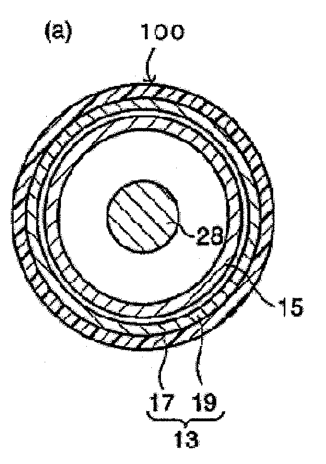
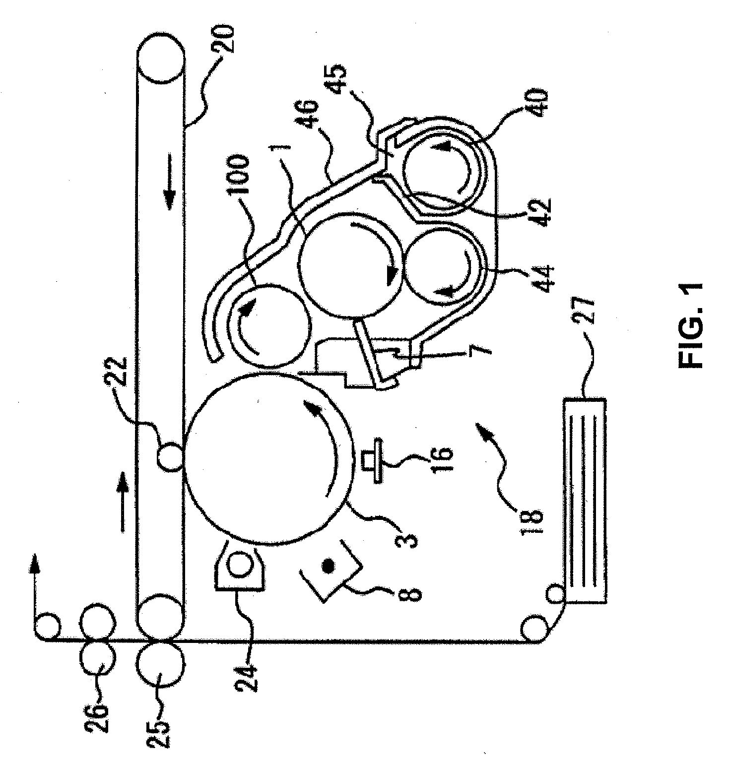
This invention relates to a developing device 18 for use in an image-forming apparatus comprising a developing roller 100 having a conductive base surface 19 which may be covered with a resin layer 17 layer comprising an ion conductive material and a silicone-modified urethane resin having an ether structure.

Description

INCORPORATION BY REFERENCE[0001]This application is based upon and claims the benefit of priority from the corresponding Japanese Patent Application No. 2008-154170, filed Jun. 12, 2008, the entire contents of which are incorporated herein by reference.FIELD OF THE INVENTION[0002]The present invention relates to a developing device for use in a copy machine, a printer, a facsimile machine, and a multifunctional machine that combines these machines, all of which utilize an electrophotographic method and an image-forming apparatus using the developing device.BACKGROUND OF THE INVENTION[0003]Conventionally known image formation methods include forming a thin layer of a toner on a developing roller by means of a magnetic brush. The magnetic brush formed on a developer supporting member supports a two-component developer. Then the toner on the developing roller develops an electrostatic latent image on an electrostatic latent image supporting member.[0004]Developing rollers used in an im...

Claims


Application Information

Patent Timeline
IPC IPC(8): G03G15/08
CPCG03G2215/0861G03G15/0818
Inventor MABUCHI, SAYOHAMAKAWA, HIROYUKIWATANABE, AKIHIROFUJISHIMA, MASASHIYAMAZAKI, HIROSHIKOTERA, ASAMI
Owner KYOCERA DOCUMENT SOLUTIONS INC
Learn More