Anchoring device

Inactive Publication Date: 2008-01-10
ARDERN FERGUS JOHNATHAN
View PDF11 Cites 16 Cited by
  • Summary
  • Abstract
  • Description
  • Claims
  • Application Information

AI Technical Summary

Benefits of technology

[0010] Preferably a plate is positioned perpendicular to the length of the shaft at or adjacent the end of the device distal from the said tapered portion. In use, once the length of the shaft has been screwed into the ground the plate engages with the ground immediately above the shaft compressing said ground around the device such that the device is more rigidly fixed in place. Additionally the plate improves the stability of the device in the ground by preventing horizontal movement of the device.
[0011] Preferably, the anchoring device further comprises a masonry bit attached to the end of the shaft adjacent said tapered portion. The incorporation of a masonry bit in this way enables the device to be used in stony ground without the risk of damage to the end of the shaft entering the ground, which might otherwise be caused by this end striking stones and other such obstructions.
[0012] Preferably the shaft further comprises a second tapered section proximal to the end of the shaft distal to the tapered portion wherein the cross-section of the shaft increases in a direction away from the first tapered portion of the shaft. The incorporation of this second tapered section improves the stability of the device once inserted in the ground by further reducing horizontal movement of the device. The incorporation of the second tapered portion of the device is b

Problems solved by technology

These devices, which comprise a shaft and blades, act as augers and displace the ground around th

Method used


Image

  • Anchoring device
  • Anchoring device
  • Anchoring device

Examples


Embodiment Construction

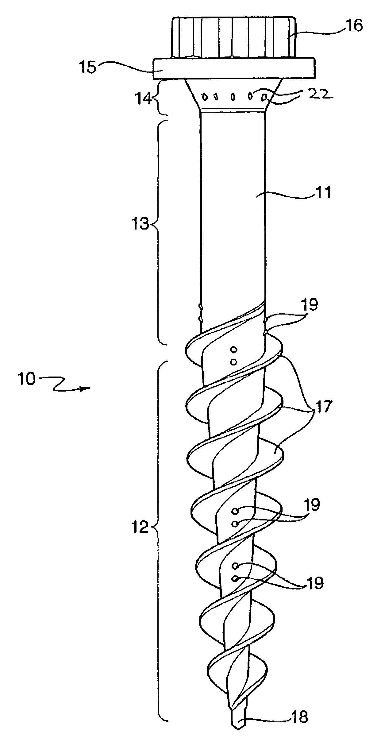
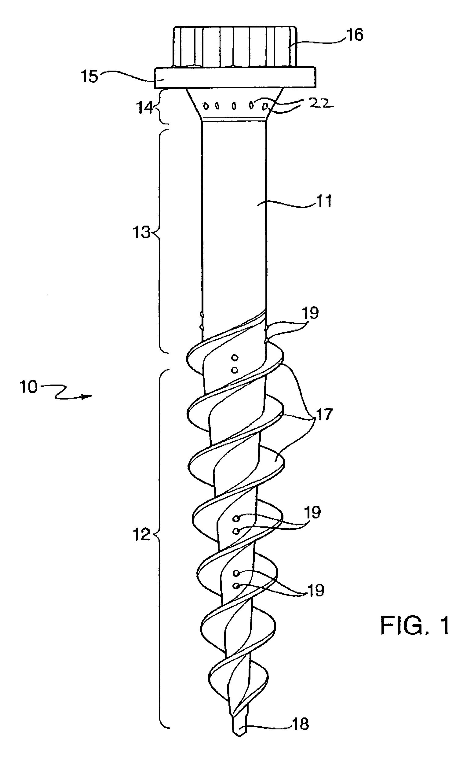
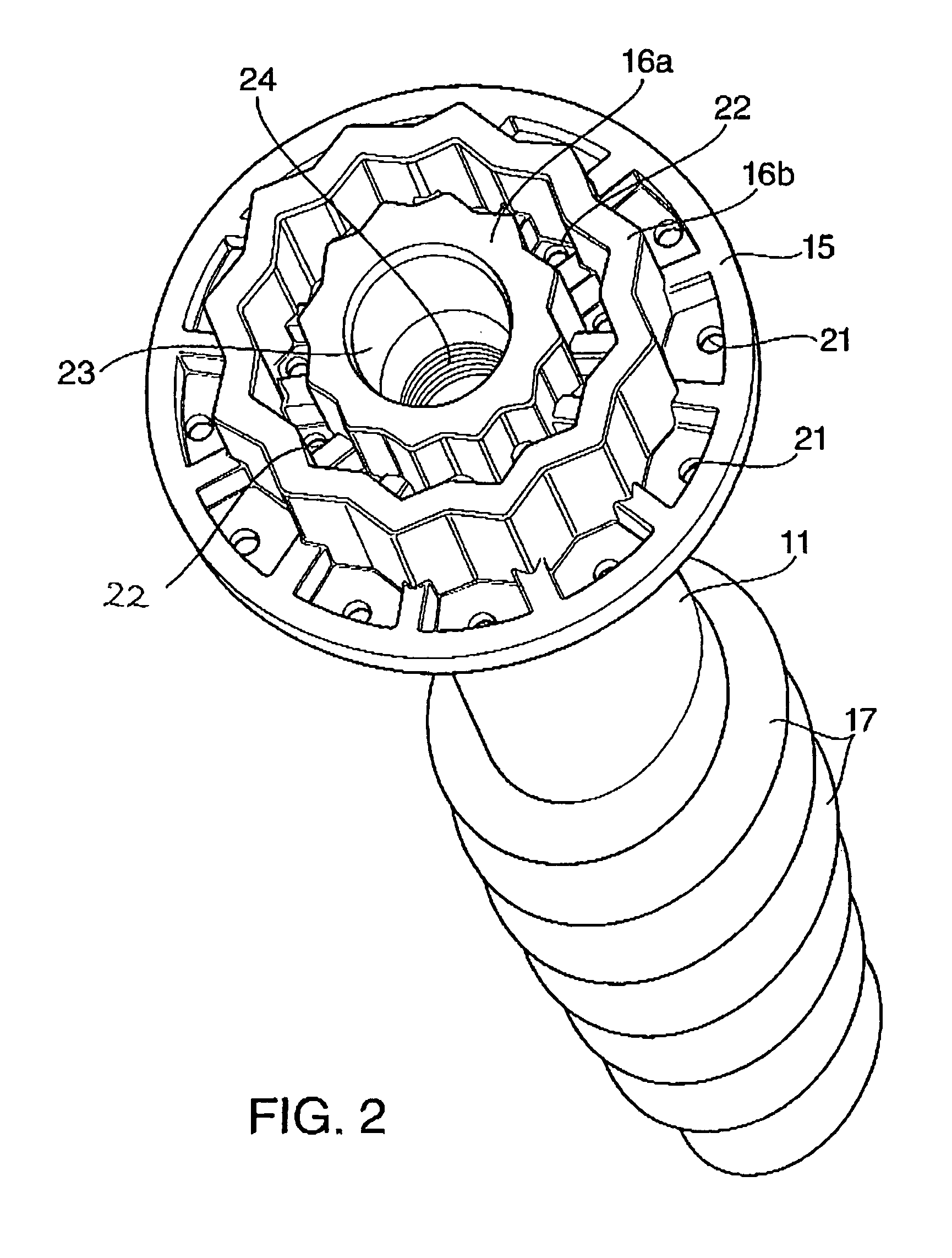
[0027] Wherever possible the same numbers have been used to indicate the same feature on different embodiments of the invention described herein. Reference is initially made to FIG. 1 of the drawings which shows a schematic side view of a ground anchor according to the present invention as generally indicated by 10. The ground anchor comprises a shaft generally indicated by 11, which has a first tapered portion 12, an untapered portion 13 and a second tapered portion 14. The anchor further comprises a plate 15 and an engagement means 16.

[0028] The cross-section of the second tapered portion of the shaft 14 increases in diameter in a direction away from the central longitudinal axis of the shaft 11.

[0029] Two helical flanges 17 are present along the first tapered portion 12. It will be noted that the first tapered portion 12 and associated helical flange 17 comprise over half, a major part, of the total length of the shaft 11. A masonry bit 18 is attached to the free end of the fir...


PUM


Abstract

An anchoring device comprising a shaft, at least part of whose length comprises a tapered portion, with at least one helical flange which runs substantially along the length of said tapered section and an engagement means to allow the device to engage with a lever wherein in use rotation of the lever about the axis of the shaft results in rotation of the device such that the tapered portion and the helical flange co-operate to drive the device into the ground.

Description

FIELD OF THE INVENTION [0001] The present invention relates to ground anchors which are generally elongate devices adapted to be inserted into the ground in order to form an anchor point to which other items, such as sign posts, flagpoles or the like can be attached. BACKGROUND [0002] One commonly known form of ground anchor comprises a hollow post or hollow rod which is driven into the ground to an appropriate depth. Anchor arms are then extended from the hollow interior into the ground and act to stabilise the post or rod, see GB2216915A. Normally this type of device is driven into the ground using a mallet or the like. [0003] PCT / GB94 / 00072 discloses a ground anchor for supporting posts or other structures which comprises a tubular socket and a twisted flat bar. In use, a hole is prepared into which the socket is inserted. The end of the bar is then inserted through a slot in the end of the socket and driven into the ground passing through the slot. Wings are also attached to the...

Claims


Application Information

Patent Timeline
IPC IPC(8): F16B35/04E04H12/22
CPCE04H12/2223E02D5/801
Inventor ARDERN, FERGUS JOHNATHAN
Owner ARDERN FERGUS JOHNATHAN
Why Eureka
Try Eureka