Muffler of scroll compressor

Active Publication Date: 2008-01-10
LG ELECTRONICS INC
View PDF22 Cites 12 Cited by
  • Summary
  • Abstract
  • Description
  • Claims
  • Application Information

AI Technical Summary

Benefits of technology

[0017]Therefore, the present invention has been made in view of the above problems, and it is an object of the present invention to provide a muffler of a scroll compressor, which can prevent high-pressure refrigerant gas, which

Problems solved by technology

If high-pressure refrigerant gas compressed in the above described compression unit is discharged through an outlet 17 of the fixed scroll 8, the high-pressure refrigerant gas imparts a direct shock to a top cap la constituting an upper end of the shell 1, thus causing generation of noise.
Generally, in the course of discharging the high-pressure refrigerant gas compressed in the compression unit through the outlet 17 of the fixed scroll 8, the high-pressure refrigerant imparts a direct shock to the top cap la of the shell 1, resulting in generation of noise.
However, the above described conventional muffler for use with the scroll compr

Method used


Image

  • Muffler of scroll compressor
  • Muffler of scroll compressor
  • Muffler of scroll compressor

Examples


first embodiment

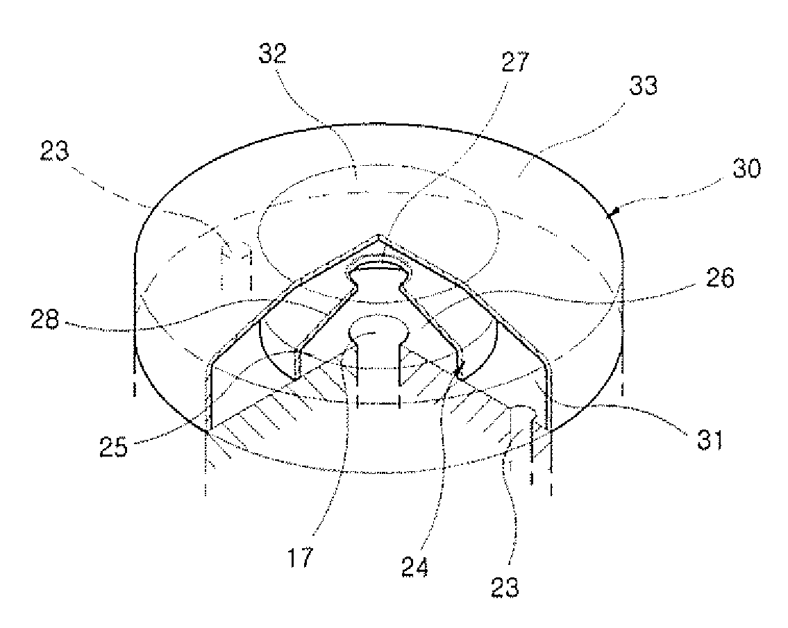
[0034]Referring to FIG. 3 illustrating a muffler according to the present invention in semi-sectional perspective view, the muffler includes a first muffler 24 and a second muffler 30. The first muffler 24 internally defines a pair of chambers above the outlet 17 of the fixed scroll 8 to communicate with the outlet 17, and is formed with a gas passage hole 27 at the center of an upper end thereof. The second muffler 30 is located around the first muffler 24 to be spaced apart from the gas passage hole 27 of the first muffler 24. The second muffler 30 internally defines a chamber, i.e. third chamber 31, including the guidance paths 23 of the fixed scroll 8.

[0035]The chambers of the first muffler 24 include a lower first chamber 25 and upper second chamber 26. The second chamber 26 is defined by an inclined conical wall 28.

[0036]The second muffler 30 has a planar gas confronting wall 32 forming the center of a top thereof, and a curved wall 33 extending downward from the planar gas co...

second embodiment

[0039]FIG. 5 is a semi-sectional perspective view illustrating a muffler according to the present invention.

[0040]As shown in FIG. 5, similar to the previously described first embodiment of the present invention, the muffler of the present embodiment includes the first muffler 24 and second muffler 30. The first muffler 24 internally defines the pair of chambers above the outlet 17 of the fixed scroll 8 to communicate with the outlet 17, and is formed with the gas passage hole 27 at the center of the upper end thereof. The second muffler 30 is located around the first muffler 24 to be spaced apart from the gas passage hole 27 of the first muffler 24, and internally defines the third chamber 31 including the guidance paths 23 of the fixed scroll 8.

[0041]The chambers of the first muffler 24 include the lower first chamber 25 and upper second chamber 26, and in particular, the second chamber 26 is defined by the inclined conical wall 28.

[0042]The second muffler 30 has the planar gas co...

third embodiment

[0044]FIG. 6 is a semi-sectional perspective view illustrating a muffler according to the present invention.

[0045]As shown in FIG. 6, similar to the previously described first and second embodiments of the present invention, the muffler of the present embodiment includes the first muffler 24 and second muffler 30. The first muffler 24 internally defines the pair of chambers above the outlet 17 of the fixed scroll 8 to communicate with the outlet 17, and is formed with the gas passage hole 27 at the center of the upper end thereof. The second muffler 30 is located around the first muffler 24 to be spaced apart from the gas passage hole 27 of the first muffler 24, and internally defines the third chamber 31 including the guidance paths 23 of the fixed scroll 8.

[0046]The chambers of the first muffler 24 include the lower first chamber 25 and upper second chamber 26, and in particular, the second chamber 26 is defined by the inclined conical wall 28.

[0047]The second muffler 30 has the p...


PUM


Abstract

Disclosed herein is a muffler of a scroll compressor. The muffler includes a first muffler having a pair of chambers defined above an outlet of a fixed scroll to communicate with the outlet and a gas passage hole formed at the center of an upper end thereof, and a second muffler located around the first muffler to be spaced apart from the gas passage hole of the first muffler and having a chamber including one or more guidance paths of the fixed scroll. The muffler can achieve reduction of operational noise, sufficient separation of oil contained in discharge gas, and efficient isolation between a discharge pressure inside the muffler and outside suction pressure.

Description

BACKGROUND OF THE INVENTION[0001]1. Field of the Invention[0002]The present invention relates to a muffler of a scroll compressor, and more particularly, to a muffler of a scroll compressor, which can achieve: reduction of operational noise; sufficient separation of oil contained in discharge gas; and efficient isolation between a discharge pressure inside the muffler and outside suction pressure.[0003]2. Description of the Related Art[0004]A general scroll compressor, as shown in FIG. 1, includes a main frame 2 and sub frame 3 mounted in a shell 1 at upper and lower locations of the shell 1, a stator 4 press-fitted in the shell 1 between the main frame 2 and the sub frame 3, and a rotor 5 disposed in the stator 4 and adapted to rotate by power applied thereto.[0005]A vertical crank shaft 6 is fixedly inserted into the center of the rotor 5 such that opposite ends thereof are rotatably supported by the main frame 2 and sub frame 3, respectively. Then, the vertical crank shaft 6 is r...

Claims


Application Information

Patent Timeline
IPC IPC(8): F01C1/02F01N7/00F01N1/08
CPCF04C18/0215F04C29/068F04C29/065F04C23/008
Inventor KIM, SEUNG-YUPPARK, HYO-KEUNLEE, DONG-SOOSUH, JEONG-HWAN
Owner LG ELECTRONICS INC
Why Eureka
Try Eureka