Three-axis motion table

a three-axis motion and motion table technology, applied in the direction of instrumentation, electric programme control, program control, etc., can solve the problems of increasing the inertia moment and weight, affecting the operation of the three-axis motion table, and affecting the operation of the hydraulic motor. , to achieve the effect of reducing the operating bandwidth, and reducing the inertia momen

Inactive Publication Date: 2006-12-28
NIHON UNIVERSITY
View PDF2 Cites 11 Cited by
  • Summary
  • Abstract
  • Description
  • Claims
  • Application Information

AI Technical Summary

Benefits of technology

[0016] The pair of both-end supporting legs (1, 1) works as a base for supporting the entire three-axis motion table (A). The pair of both-end supporting legs (1, 1) is more stable than a base (B in FIG. 10) according to the conventional technology using only one vertical rotation axis for supporting one end. The pair of both-end supporting legs (1, 1) is capable of miniaturization and weight saving.
[0019] This configuration makes it possible to provide further weight saving by maintaining the rigidity.
[0025] According to the present invention, the following configuration is preferable. There are provided a rotation angle sensor from each of three motor axes and an angular speed detection circuit. An angular speed signal is compared with a target angle signal and a target angular speed signal to generate a control current for minimizing a difference between the target angle and the target angular speed. The first through third motors are controlled to achieve a target rotation angle and a target rotational speed in the three-dimensional space (Claim 3).
[0026] When this configuration is used to measure rotation angles for the three axes at a specified control interval, an external computer can easily calculate moments caused by the unbalance. It is possible to control unbalanced moments resulting from weights of the motors (M2 and M3).
[0030] In this manner, the finite element method is used to analyze modes of the frames for three axes before the manufacture. It is possible to accurately comprehend frequencies for the frame's low frequency modes compared to the conventional design based on the “intuition.” This makes it possible to previously ensure sufficient separation from operation frequencies for the three-axis motion table. There is no need to ensure the rigidity more than necessary. As a result, it is possible to avoid necessity of manufacturing frames having unnecessarily large inertia moments or weights. Operation bandwidths can be also improved.
[0031] Further, a three-axis motion table according to the present invention is preferably configured as follows. There is provided a rotation angle sensor from each of three motor axes. A signal from the rotation angle sensor is electrically processed to obtain an angular speed signal. The angular speed signal is compared with a target angle signal and a target angular speed signal to generate a control signal for minimizing a difference between the target angle and the target angular speed and controlling the first through third motors and to achieve a target rotation angle and a target rotational speed. A minimum frequency for a vibration domain becomes greater than or equal to a specified value with reference to a maximum frequency for an operation bandwidth (Claim 5).

Problems solved by technology

Accordingly, the three-axis motion table is inevitably subject to a large inertia moment and needs to be driven by a hydraulic motor that provides a large torque.
This also has been a cause of increasing the inertia moment and the weight.
Furthermore, a hydraulic motor is inappropriate for continuous rotations in the same direction and involves a narrow range of adjusting rotational speeds.
Such tendency (toward the design of using highly rigid materials) also causes the inertia moment and the weight to increase and results in heavy usage of hydraulic motors capable of a large torque.
It is impossible to eliminate an elastic vibration signal from signals detected by a sensor mounted on the simulated object using a lowpass filter and the other means.
None of the proposals solves the above-mentioned problems.

Method used


Image

  • Three-axis motion table
  • Three-axis motion table
  • Three-axis motion table

Examples


first embodiment

[0044] The first embodiment will be described with reference to FIGS. 1 through 5.

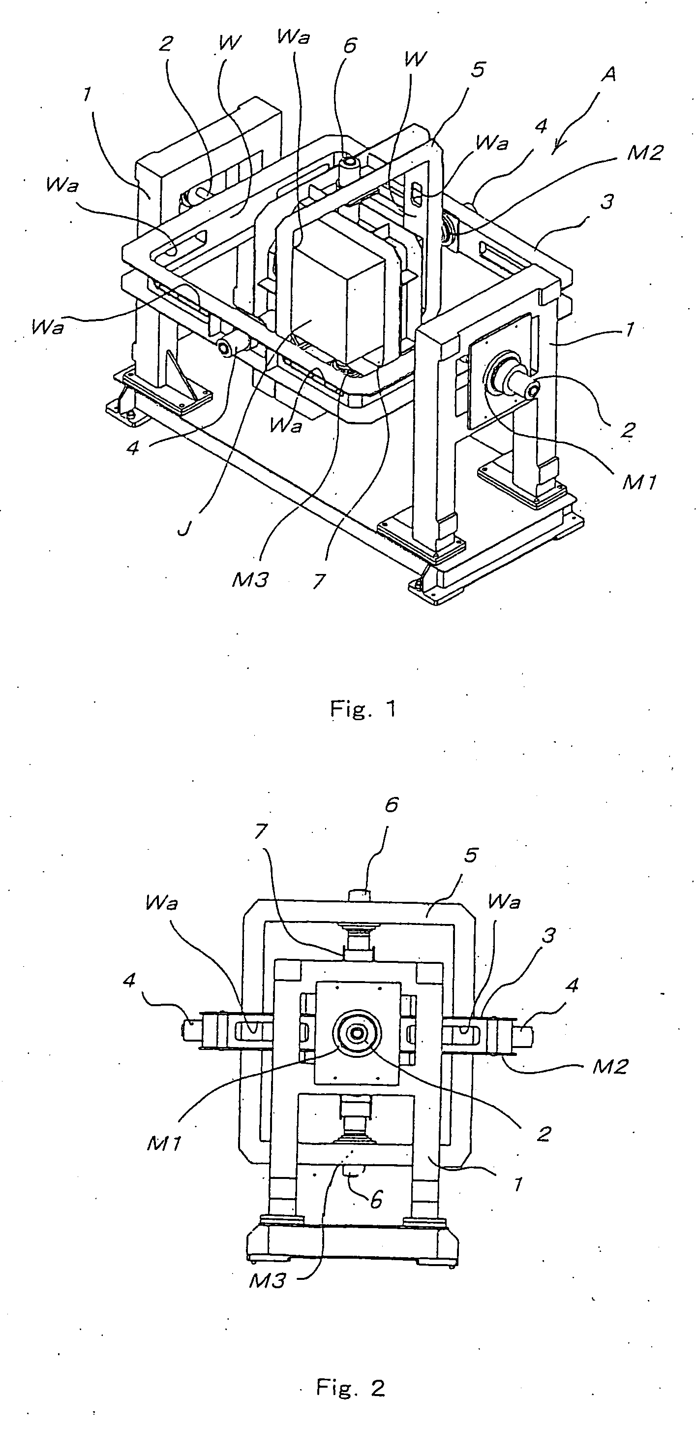
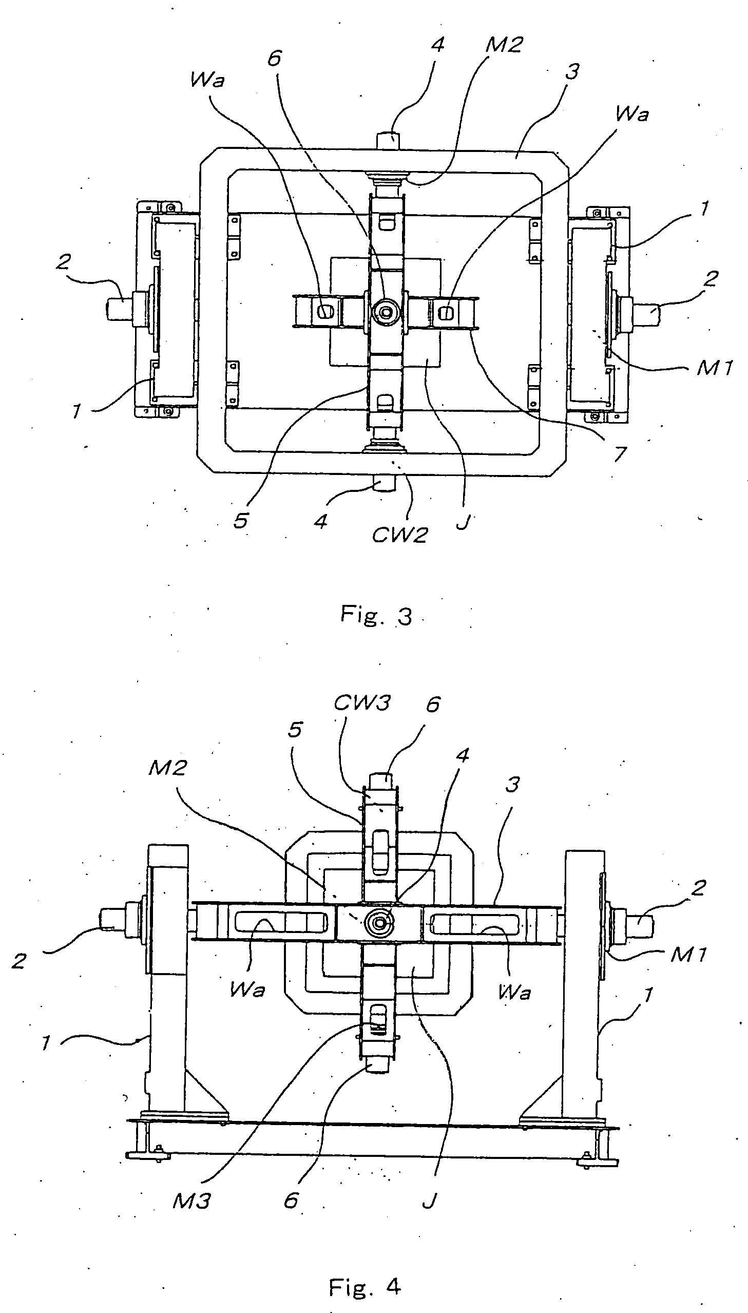
[0045]FIG. 1 is the perspective view of a three-axis motion table indicated by reference symbol A. FIGS. 2 through 4 are the front view, the top view, and the side view of the three-axis motion table A, respectively.

[0046] In the three-axis motion table A according to FIGS. 1 through 4, an outside frame 3 is rotatably attached around a first rotation axis 2 bridged by a pair of bridge-shaped supporting legs (1, 1) opposite to each other.

[0047] The outside frame 3 is rotatably attached with an intermediate frame 5 around a second rotation axis 4 bridged at a position opposite to the outside frame 3.

[0048] The intermediate frame 5 is rotatably attached with an inside frame 7 around a third rotation axis 6 bridged at a position opposite to the intermediate frame 5.

[0049] The inside frame 7 has a mechanism for holding a simulated object J such as an artificial satellite. One of the supporting legs (1, ...

second embodiment

[0061] The second embodiment as shown in FIGS. 6 and 7 provides such automatic control.

[0062] Except elimination of the counter weights CW2 and CW3, the second embodiment provides an external view similar to that of the first embodiment as mentioned above.

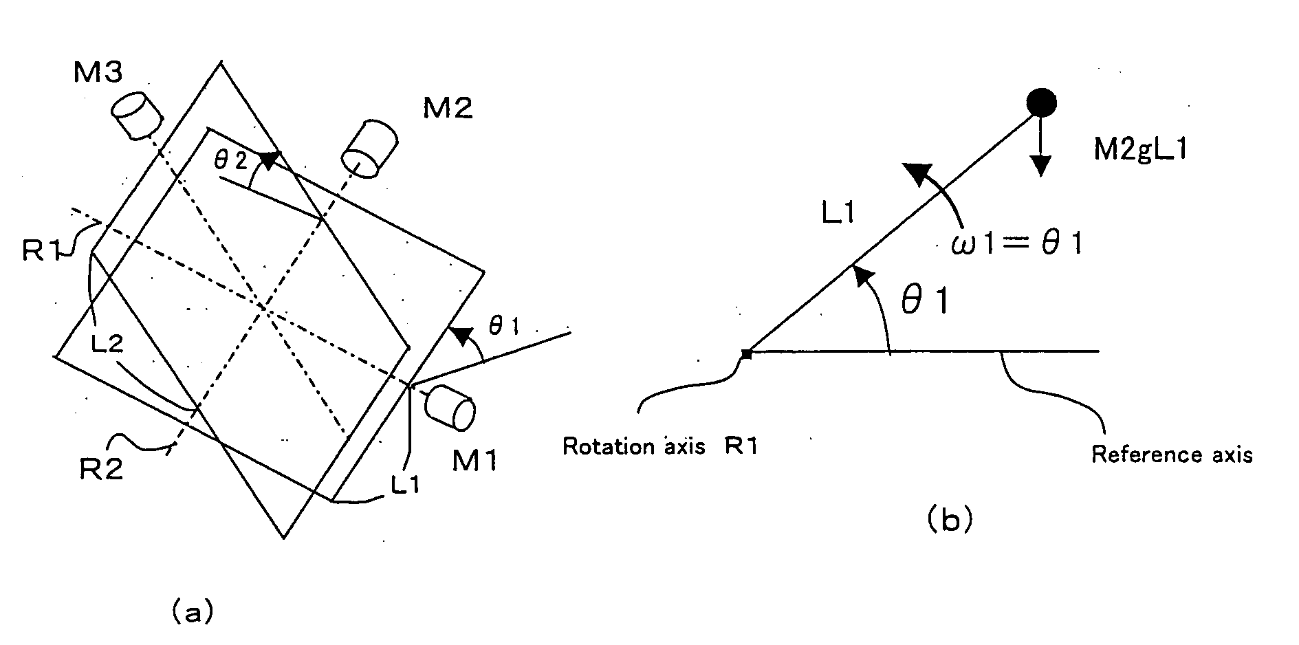
[0063] The second embodiment calculates a moment due to unbalance (resulting from weights of the electric motors M2 and M3) caused by elimination of the counter weights CW2 and CW3 at a specified control interval. To cancel effects of such moment, the embodiment provides control to add a cancellation signal to a target signal for the rotation angle or the angular speed of the electric motors M1 and M2.

[0064] With reference to FIG. 6, let us assume that M2 and M3 respectively denote masses of the electric motors (M2, M3); g denotes gravitational acceleration; L1 and L2 respectively denote distances from rotation centers of the outside frame and the intermediate frame to the corresponding electric motors; θ1 and θ2 denote rotation ...


PUM


Abstract

The present invention aims at providing a three-axis motion table capable of ensuring smooth rotations around three rotation axes orthogonal to each other and decreasing an overall weight. The three-axis motion table according to the present invention has an outside frame (3), an (e.g., approximately square) intermediate frame (5), and an (e.g., approximately square) inside frame (7). The outside frame (3) is rotatably mounted around a first rotation axis (2) by means of a pair of both-end supporting legs (1, 1). The intermediate frame (5) is rotatably mounted around a second rotation axis (4) by means of the outside frame (3). The inside frame (7) is rotatably mounted around a third rotation axis (6) by means of the intermediate frame (5). The inside frame (7) has a holding mechanism for a tested model (J). One of the both-end supporting legs (1, 1) is provided with a first motor (M1) to rotate the outside frame (3). The outside frame (3) is provided with a second motor (M2) to rotate the intermediate frame (5). The intermediate frame (5) is provided with a third motor (M3) to rotate the inside frame (7). According to the above-mentioned configuration, the first through third motors (M1 through M3) rotate. The inside frame (7) holding the tested model (J) rotates in the space inside the intermediate frame (5). The intermediate frame (5) rotates in the space inside the outside frame (3). In this manner, rotations are provided around the three rotation axes (2, 4, 6) orthogonal to each other. The pair of both-end supporting legs (1, 1) works as a base for supporting the entire three-axis motion table (A). The pair of both-end supporting legs (1, 1) is more stable than a base (B in FIG. 10) according to the conventional technology using only one vertical rotation axis for supporting one end. The pair of both-end supporting legs (1, 1) is capable of miniaturization and weight saving.

Description

TECHNICAL FIELD [0001] The present invention relates to a three-axis motion table and its rotation control in terms of an attitude control apparatus for simulating and testing rotational motions of aircraft, rockets, artificial satellites, and various vehicles (hereafter referred to as a “simulated object”). BACKGROUND ART [0002] Many conventional three-axis motion tables are configured so that one rotation axis P vertically supports the whole of a three-axis motion table J as shown in FIG. 10. [0003] According to the example in FIG. 10, the single rotation axis supports the whole of the three-axis motion table J. The mechanism of a base portion B for supporting the rotation axis P (a vertically extending rotation axis) becomes large and increases the weight so as to enable the reliable support in all directions. [0004] For example, let us consider a case of mounting an experimentally produced artificial satellite on the three-axis motion table and testing attitude control motions i...

Claims


Application Information

Patent Timeline
Patent Type & Authority Applications(United States)
IPC IPC(8): G05B19/04G01C19/00B23Q1/54
CPCB23Q1/5412
Inventor SHIMADA, YUZOUCHIYAMA, KENJI
Owner NIHON UNIVERSITY
Why Eureka
Try Eureka