[0014] In accordance with the present invention, this object is attained by compensating for a speed related decrease in ink delivery, which tends to occur as a production speed of a
printing press increases. This compensation in ink delivery decrease, with increasing production speed is accommodated by reducing the ink
viscosity. This change in ink
viscosity is done by varying the outer surface temperature of ink-carrying rollers and cylinders.
[0015] The advantages to be obtained by the method and the device of the present invention lie, on the one hand, in that, by the use of adjustable temperature-regulating devices, different parameters of the printing ink, and in particular its viscosity and tackiness, are specifically influenced. This influencing is able to be accomplished selectively and in accordance with various requirements, in order, on the one hand, to match the transport of the printing ink to the prevailing operating conditions in the
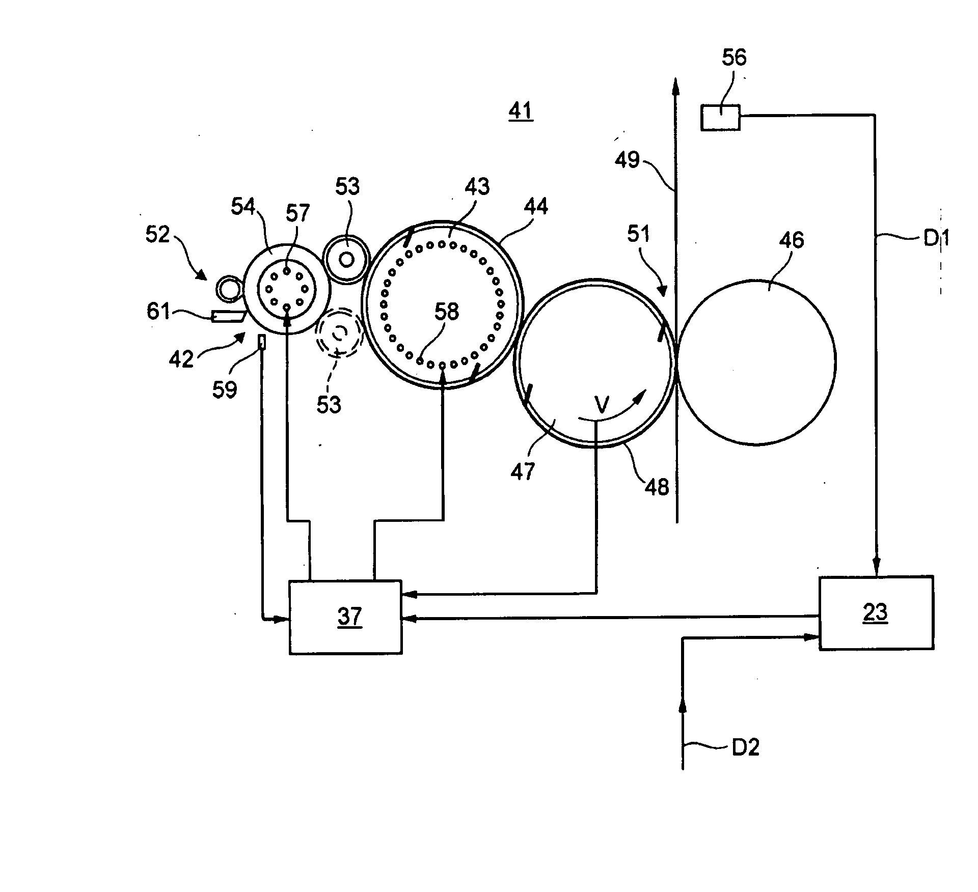
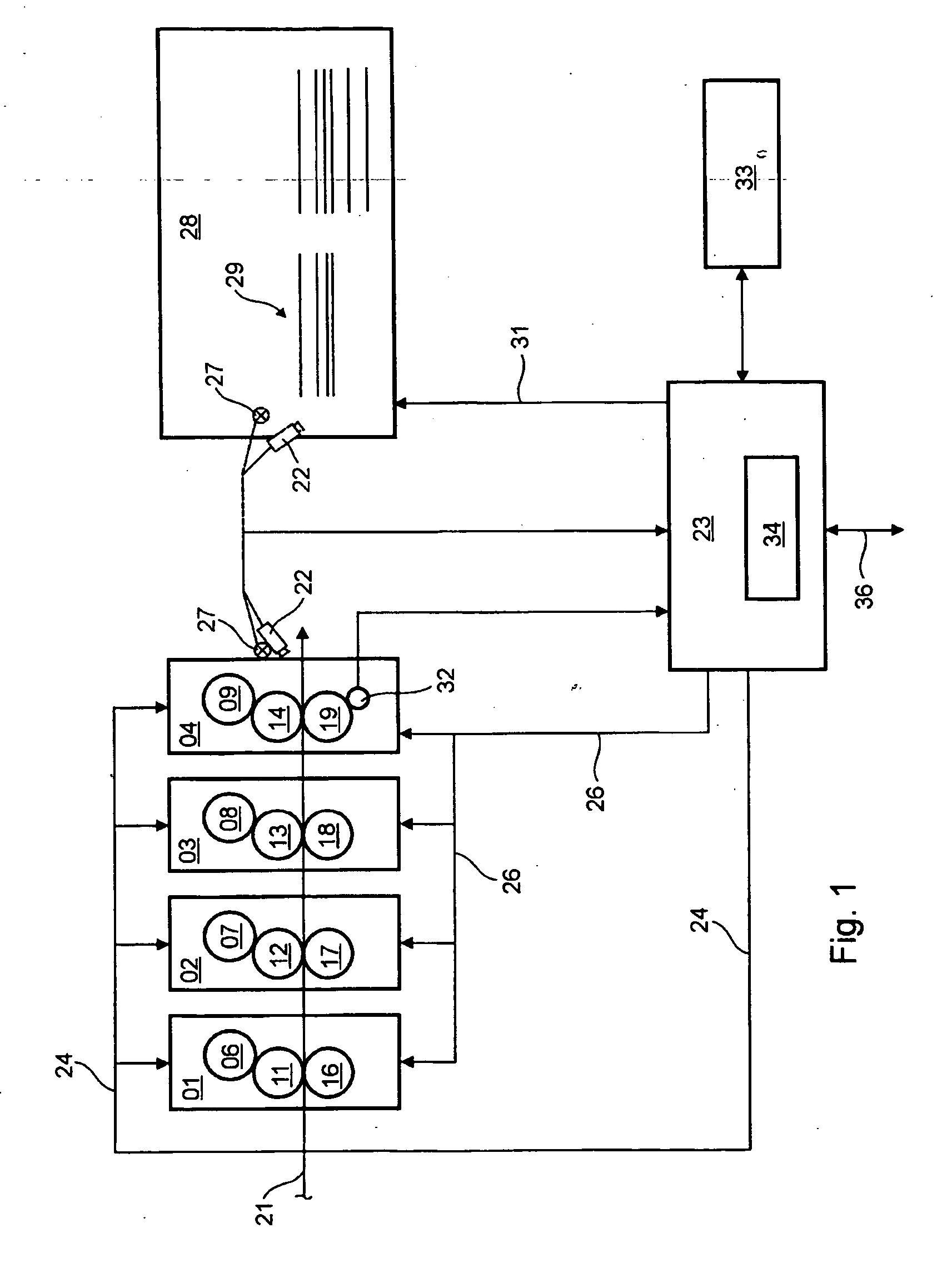
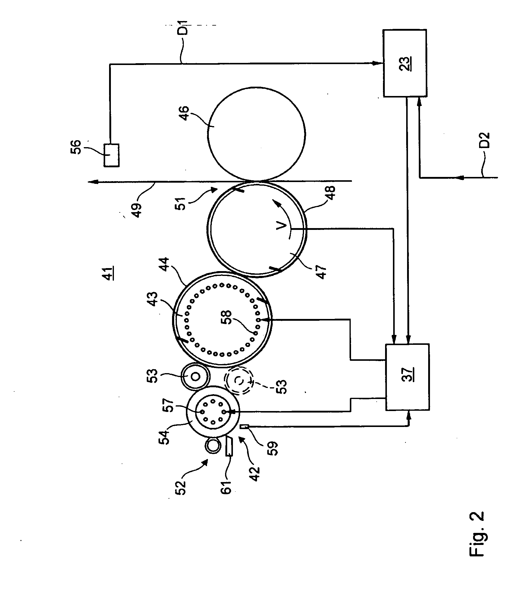
printing press and on the other hand, to prevent pulling and / or smudging of the printing ink. As a result, for example a conveying rate of a printing ink, by the operation of a roller that dips printing ink from a reservoir and transfers it to an adjoining rotating body, such as, for example, a screen roller, is kept at least approximately constant. In the case of an increase in the production speed of the
printing press, an amount of ink, which is maintained as even as possible, is conveyed to the material to be imprinted. This can be done in
spite of a decrease in the capability of the screen roller for transferring printing ink which decrease in capability goes along with this increase in production speed, because of an increasingly incomplete emptying of its cups. On the other hand, the value of the tackiness of the printing ink being transported by the forme cylinder is kept within a range that is suitable for the printing process by the provision of a setting of the temperature at the outer surface, of in particular the forme cylinder. This temperature setting is a function of the production speed of the printing press. Pulling of the printing ink on the surface of the material to be imprinted is avoided in particular. As a function of the production speed of the printing press, the printing ink is matched, with regard to its splitting and its adhesion capabilities, by setting its temperature in accordance with the production requirements. The printing ink temperature is set indirectly by setting the temperature at the outer surface of a rotating body which conveys this printing ink. To avoid waste, which would occur as a result of incorrect temperature-dependent properties of the printing ink being employed, the changed chronological behavior, for performing the matching of the production speed of the printing press, is taken into consideration in the case of an intended change of the production speed of the printing press. The possibility of changing, such as, for example, manually, the
machine conditions within defined limits and, in this way, for executing a
fine tuning, which is directed to providing a good quality of the printed product, is also taken into consideration. All of these measures contribute to keeping the quality of a printed product which is generated by the use of the printing press at a high level, in
spite of a change in the production speed of a printing press.

