Methods and Apparatus for Multiple Part Missile

Active Publication Date: 2008-01-17
RAYTHEON CO
View PDF28 Cites 11 Cited by
  • Summary
  • Abstract
  • Description
  • Claims
  • Application Information

AI Technical Summary

Problems solved by technology

These methods may not result in a smooth outer profile of the missile.
While these methods mate subassemblies of missiles, they require multiple steps and may require more than one person to perform.

Method used


Image

  • Methods and Apparatus for Multiple Part Missile
  • Methods and Apparatus for Multiple Part Missile
  • Methods and Apparatus for Multiple Part Missile

Examples


Embodiment Construction

[0014]The present invention may be described in terms of functional block components and various processing steps. Such functional blocks may be realized by any number of mechanical or electrical components configured to perform the specified functions and achieve the various results. For example, the present invention may employ various missile subassemblies and joints, e.g., adapters, snap rings, electrical connections, and the like, which may carry out a variety of functions. In addition, the present invention may be practiced in conjunction with any number of missile assembly processes, and the system described is merely one exemplary application for the invention. Further, the present invention may employ any number of conventional techniques for assembling missile halves, mating adapters, electrical connections, and the like.

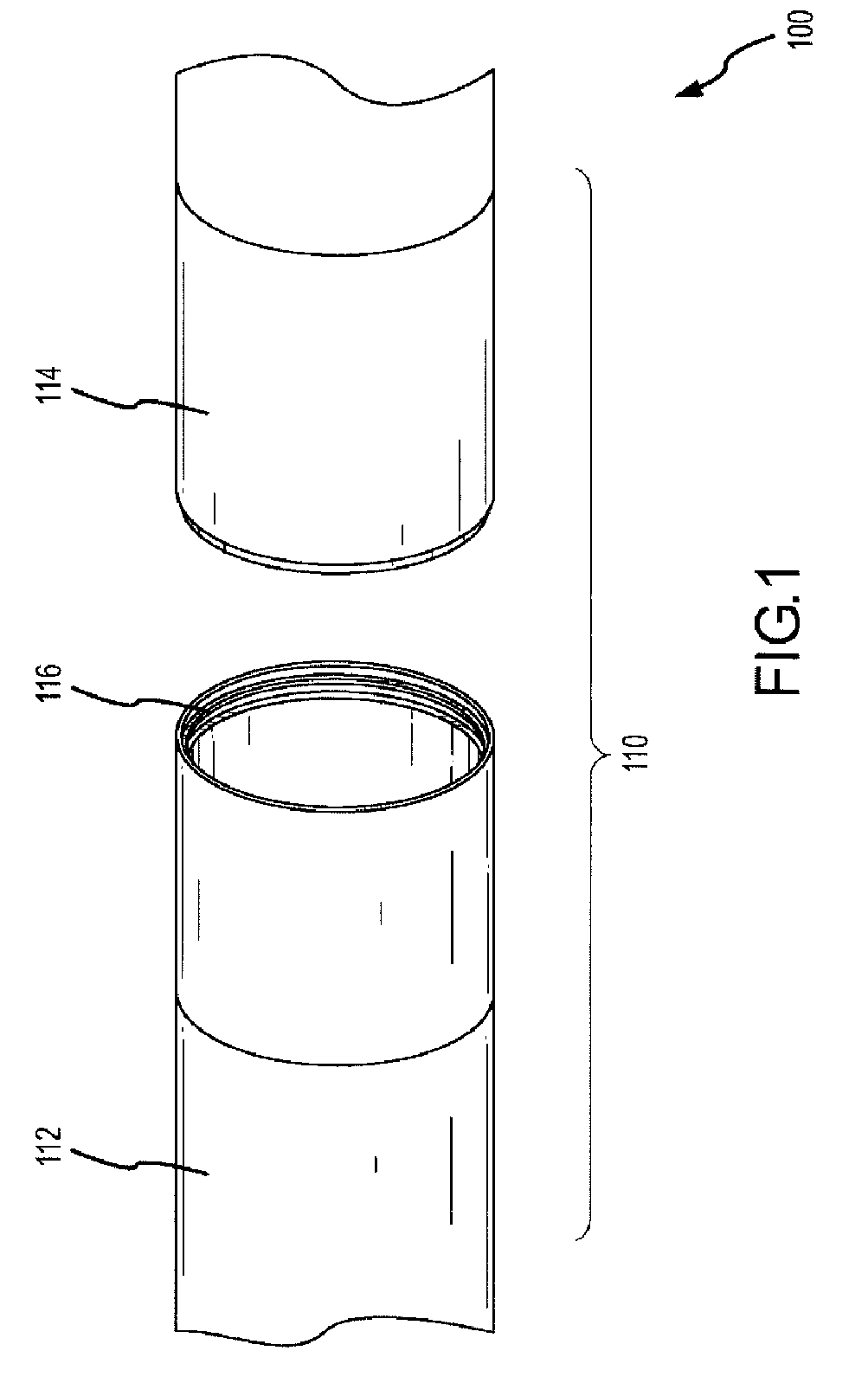
[0015]Referring now to FIG. 1, methods and apparatus for a multiple-part missile according to various aspects of the present invention may operate in conj...


PUM


Abstract

Methods and apparatus for a multiple part missile according to various aspects of the present invention may operate in conjunction with a first missile part having a first groove formed in a surface of the first missile part and a second missile part having a second groove. A snap ring may be configured to engage the first groove and the second groove.

Description

FIELD OF THE INVENTION[0001]The invention relates to missiles, and more particularly, to methods and apparatus for missiles comprising multiple elements.BACKGROUND OF THE INVENTION[0002]Mobile weapons, such as missiles, are often more useful if they can be assembled and disassembled in the field. Current methods of mechanical missile assembly include the use of fasteners such as screws and clamps. These methods may not result in a smooth outer profile of the missile. Electrical connections of missile subassemblies require separate processes. While these methods mate subassemblies of missiles, they require multiple steps and may require more than one person to perform.SUMMARY OF THE INVENTION[0003]Methods and apparatus for a multiple part missile according to various aspects of the present invention may operate in conjunction with a first missile part having a first groove formed in a surface of the first missile part and a second missile part having a second groove. A snap ring may ...

Claims


Application Information

Patent Timeline
IPC IPC(8): F42B15/10
CPCF42B33/001F42B15/36
Inventor STIMPSON, MICHAEL V.
Owner RAYTHEON CO
Why Eureka
Try Eureka