Flight control actuation system

a technology of flight control and actuator, applied in the direction of aircraft power plants, power amplification, transportation and packaging, etc., can solve the problems of affecting flight vehicle weight constraints and aerodynamic envelope limitations, design does not account for significant variances from the normal operational range, and risks of overloading the electrical actuator, so as to reduce the load on the electromechanical actuator

Inactive Publication Date: 2006-03-07
HONEYWELL INT INC
View PDF11 Cites 57 Cited by
  • Summary
  • Abstract
  • Description
  • Claims
  • Application Information

AI Technical Summary

Benefits of technology

[0013]In one aspect of the present invention, a flight control actuation system comprises a control means operable in response to an input for generating a control signal, an electromechanical actuator responsive to the control signal, for operating a flight control surface, and a pneumatic actuator for assisting the electromechanical actuator by reducing the load on the electromechanical actuator.
[0014]In another aspect of the present invention, a flight control actuation system comprises a control means operable in response to an input for generating a control signal, an electromechanical actuator responsive to the control signal, for operating a flight control surface, and a pneumatic actuator for assisting the electromechanical actuator by reducing the load on the electromechanical actuator, wherein the pneumatic actuator initializes when the current in the electromechanical actuator increases beyond a predetermined amperage.
[0016]In another aspect of the present invention, a method is also disclosed for operating a flight control actuation system, the system being adapted to activate at least one pneumatic actuator in response to at least one signal produced by a control surface actuation signal system for positioning at least one control surface. The method comprises the steps of (a) receiving an input signal in the form of a position demand providing an instruction for deflecting a control surface to a new position and (b) the controller generating a corresponding control signal for operating an electromechanical actuator. In addition the method comprises the steps of (c) receiving a feedback signal in the form of an electrical current measurement at the electromechanical actuator, (d) comparing the electrical current measurement to a predetermined electrical current value, and (e) the controller generating a corresponding pressurization control signal for operating a pneumatic actuator for reducing the load on the electromechanical actuator.

Problems solved by technology

This system design does not account for significant variances from the normal operational range of the electrically powered actuator, such as control surface flutter and shockwave conditions.
To account for the resultant high control surface loads, the actuator systems must be large in size and mass, negatively impacting flight vehicle weight constraints and aerodynamic envelope limitations.
Additionally, large flight vehicles traveling at high speeds introduce risks of overloading the electrical actuator from the greater forces needed to manipulate the flight control surfaces in such situations.
This system's drawbacks are lower output forces than conventional actuator systems, and the excess size and mass added to the flight vehicle from the use of control tabs.
None of the prior art is specifically intended for lightweight, high-speed applications, and some suffer from one or more of the following disadvantages:a) excessive mass and size.b) inability to accommodate flutter or shockwave effects.c) increased cooling requirements.d) low achievable output forces.e) inferior aerodynamic envelope conditions.f) inability to use detected electrical actuator current variations.

Method used


Image

  • Flight control actuation system
  • Flight control actuation system
  • Flight control actuation system

Examples


Embodiment Construction

[0030]The following detailed description is of the best currently contemplated modes of carrying out the invention. The description is not to be taken in a limiting sense, but is made merely for the purpose of illustrating the general principles of the invention, since the scope of the invention is best defined by the appended claims.

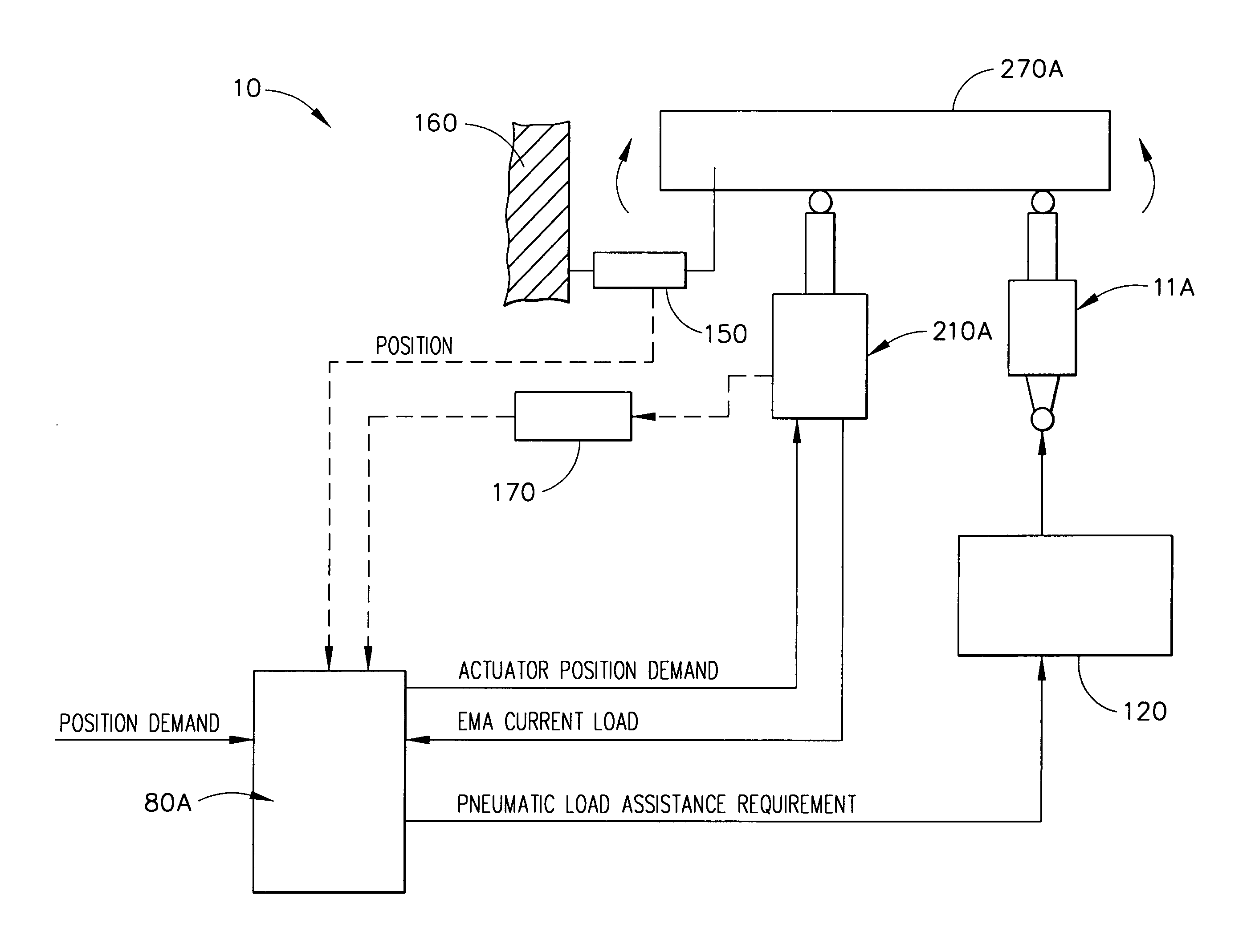
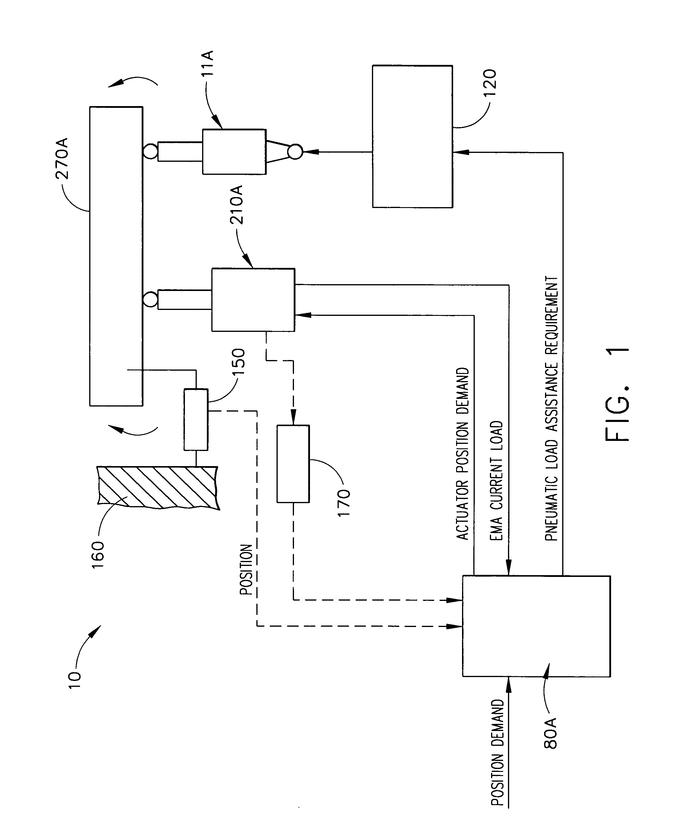
[0031]The present invention may comprise a position controlled actuation system to accurately position a control surface while using an auxiliary actuation system to provide a load trim function for the position controlled actuation system. The present invention may allow the use of an auxiliary actuator to provide a large portion of the force to control the actuation system position. This may limit the smaller portion of the load, provided by a positioning actuator, to a level that is within the capability of a relatively low power positioning actuator.

[0032]The invention is useful for controlling all types of flight vehicles, including, but not limite...


PUM


Abstract

A flight control actuation system comprises a controller, electromechanical actuator and a pneumatic actuator. During normal operation, only the electromechanical actuator is needed to operate a flight control surface. When the electromechanical actuator load level exceeds 40 amps positive, the controller activates the pneumatic actuator to offset electromechanical actuator loads to assist the manipulation of flight control surfaces. The assistance from the pneumatic load assist actuator enables the use of an electromechanical actuator that is smaller in size and mass, requires less power, needs less cooling processes, achieves high output forces and adapts to electrical current variations. The flight control actuation system is adapted for aircraft, spacecraft, missiles, and other flight vehicles, especially flight vehicles that are large in size and travel at high velocities.

Description

CROSS REFERENCE TO RELATED APPLICATION[0001]This is a Divisional application of U.S. application Ser. No. 10 / 410,413 filed Apr. 7, 2003 now U.S. Pat. No. 6,827,311.GOVERNMENT RIGHTS[0002]The invention described herein was made in the performance of work under NASA Cooperative Agreement No. NCC8-115, dated Jul. 1, 1996, and is subject to the provisions of Section 305 of the National Aeronautics and Space Act of 1958 (42 U.S.C. 2457). The Government has certain rights in this invention.BACKGROUND OF THE INVENTION[0003]This present invention relates generally to flight control actuation systems and, more specifically, to a method and apparatus for a dual actuator control system, containing at least one electromechanical actuator and at least one pneumatic actuator. The present invention concerns actuator systems for controlling flight control surfaces on aircraft, spacecraft, missiles, and other flight vehicles.[0004]Actuator servomechanism systems are used to manipulate flight control...

Claims


Application Information

Patent Timeline
Patent Type & Authority Patents(United States)
IPC IPC(8): B64C13/40B64C13/48B64C13/42B64C13/50
CPCB64C13/50B64C13/42
Inventor WINGETT, PAUL T.GAINES, LOUIE T.EVANS, PAUL S.KERN, JAMES I.
Owner HONEYWELL INT INC
Why Eureka
Try Eureka