
Laser beam source for a directional infrared countermeasures (DIRCM) weapon system

a weapon system and laser beam technology, applied in the direction of laser details, instruments, defence devices, etc., can solve the problems of not economically practicable known systems, inconvenient to use, and limited range of laser beams

Inactive Publication Date: 2003-07-01
EADS DEUT GMBH
View PDF7 Cites 57 Cited by
  • Summary
  • Abstract
  • Description
  • Claims
  • Application Information

AI Technical Summary

Benefits of technology

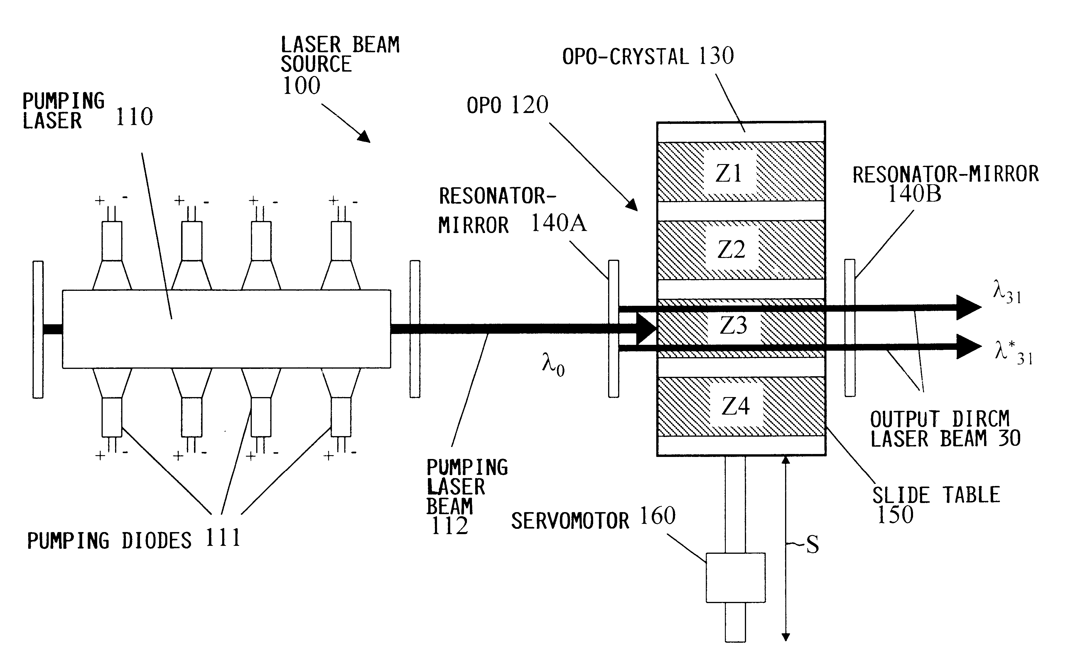
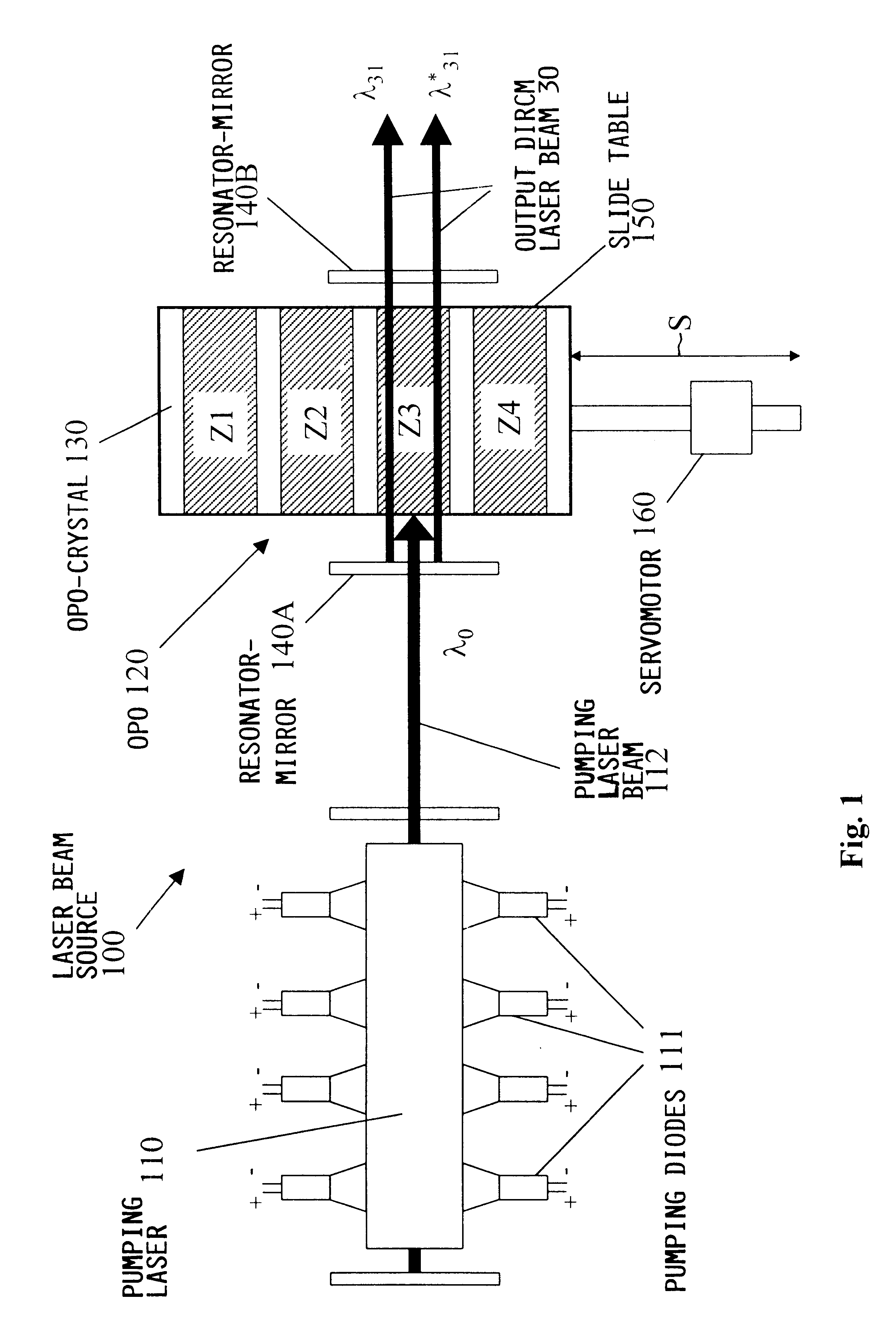
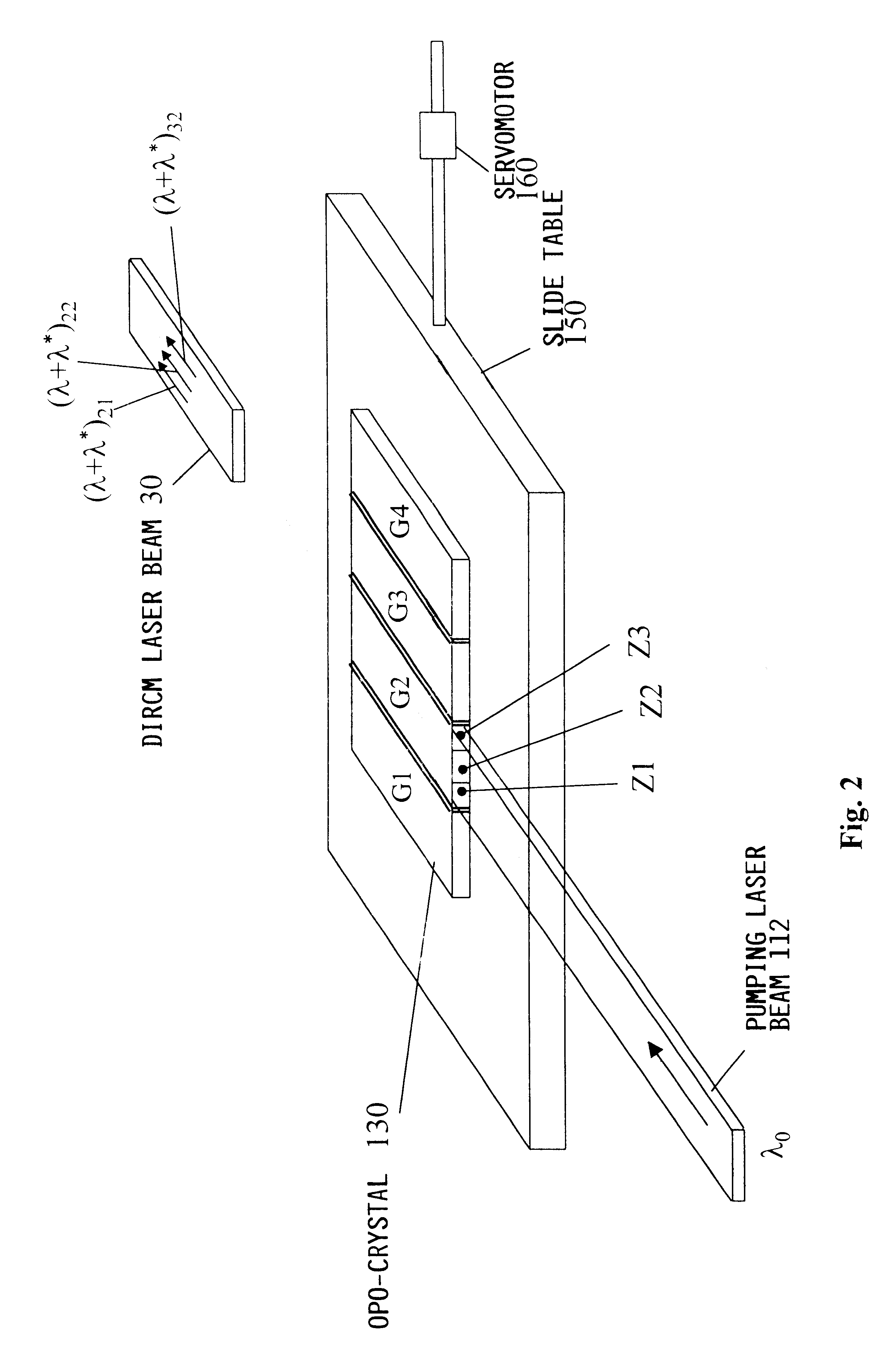
The laser beam generator arrangement according to the invention comprises a semiconductor diode pumped laser as a pumping laser in combination with an optical parametric oscillator including a non-linear crystal. The crystal preferably comprises a plurality of different periodically polarized crystal zones arranged successively adjacent one another along the crystal, whereby the crystal zones respectively have different lattice spacings or lattice constants respectively correlated to the different wavelengths that are to be produced. By moving the crystal so that a selected one of the crystal zones is positioned in alignment with the pumping laser beam, it is possible to produce the desired output wavelength of the laser beam.

Problems solved by technology

For this reason, the known systems are not economically practical in view of their complex construction and operation.
Another disadvantage of the above described manner of generating the necessary laser beam using OPOs is that generally only a single respective wavelength will be available within the desired wavelength range.
*) is generally not suitable for DIRCM purposes due to its inappropriate wavelength and intensity.
This limitation of the known systems is a serious disadvantage.
Still another disadvantage of previously known laser beam sources for DIRCM weapon systems is that the emitted laser beam having a fixed wavelength is subject to relatively simple countermeasures.
As a result, all of the DIRCM weapon systems employing a laser beam at a this particular wavelength will be ineffective.

Method used


Image

  • Laser beam source for a directional infrared countermeasures (DIRCM) weapon system
  • Laser beam source for a directional infrared countermeasures (DIRCM) weapon system
  • Laser beam source for a directional infrared countermeasures (DIRCM) weapon system

Examples


Embodiment Construction

FIG. 4 schematically illustrates a representative application or situation in which the present invention can be used. A guided missile 50 having an IR target seeking head 60 has been fired at a target aircraft 10 from a shoulder-supported launcher or firing station 40 carried by a soldier. Infrared detectors in the IR target-seeking head 60 of the missile 50 are intended to detect and track the engine heat of the target aircraft 10, and thereby guide the missile 50 into impact with the aircraft 10. The target aircraft 10, however, is equipped with a DIRCM weapon system 20 including a laser beam source according to the present invention, as well as circuits and devices for target acquisition, recognition and tracking, as well as devices for directing the laser beam emitted by the inventive beam source.

The DIRCM weapon system 20 detects the incoming guided missile 50, and uses the laser source according to the invention to generate a suitable DIRCM laser beam 30 and then directs the ...


PUM


Abstract

A laser beam source and an operating method thereof is provided for a directional infrared countermeasures (DIRCM) weapon system for defensively countering guided missiles having infrared seeking heads, by directing an infrared laser beam at the guided missile so as to disorient, saturate, or irreversibly destroy the IR detectors and circuitry arranged in the target seeking head. The power, pulse frequency and spectral composition of the laser beam is adjustable and selectable as required to adapt to any particular defensive engagement. To achieve this, the laser beam source comprises an Nd:YAG pumping laser and an optical parametric oscillator including an oscillator crystal arranged in a resonator cavity. The crystal includes a plurality of different periodically polarized crystal zones having different lattice constants. The adjacent zones can be grouped together into selectable crystal zone groups. The beam cross-section of the pumping laser beam corresponds to the cross-section of a single crystal zone or of a crystal zone group encompassing plural zones. The crystal is arranged on a slide table that is slidably displaceable by a servomotor, to move a selected crystal zone or group into the path of the pumping laser beam. Thereby the wavelength components and the relative intensities thereof of the output laser beam can easily be selectively adjusted.

Description

PRIORITY CLAIMThis application is based on and claims the priority under 35 U.S.C. .sctn.119 of German Patent Application 197 45 782.1, filed on Oct. 16, 1997, the entire disclosure of which is incorporated herein by reference.The invention relates to a laser beam source for a directional infrared countermeasures (DIRCM) weapon system especially for use in the self-defense of an aircraft against a flying body such as a missile having an infrared (IR) seeking head.BACKGROUND INFORMATIONThe use of guided missiles for attacking aircraft, tanks, other military vehicles, and ground-based installations is well known. Such guided missiles especially include IR-seeking or heat-seeking missiles having an IR-seeking head that includes IR-sensors to seek out, locate, identify, and track the IR-signature of IR-emissions from the intended target aircraft or the like. By tracking and following the IR-emissions of the target body, the guided missile guides itself to the target body, even if the ta...

Claims


Application Information

Patent Timeline
IPC IPC(8): F41H13/00G01S7/495G01S7/48F41H11/02
CPCF41H11/02F41H13/0062G01S7/495
Inventor SEPP, GUNTHERPROTZ, RUDOLF
Owner EADS DEUT GMBH
Learn More