
Molded plastic mascara brush

Inactive Publication Date: 2008-01-17
ALBEA SERVICES SAS
View PDF10 Cites 92 Cited by
  • Summary
  • Abstract
  • Description
  • Claims
  • Application Information

AI Technical Summary

Benefits of technology

[0007]As used herein, the term “shape-retaining wire” refers to an elongated element, typically or usually made of metal and conveniently a length of conventional wire, which is substantially non-resilient so that it retains its shape. This shape-retaining wire serves as a stiffener for the plastic brush core, holding it in a stable axial configuration and thereby, for example, enabling the core and bristles to be molded of a softer (more flexible) material than would otherwise be possible.
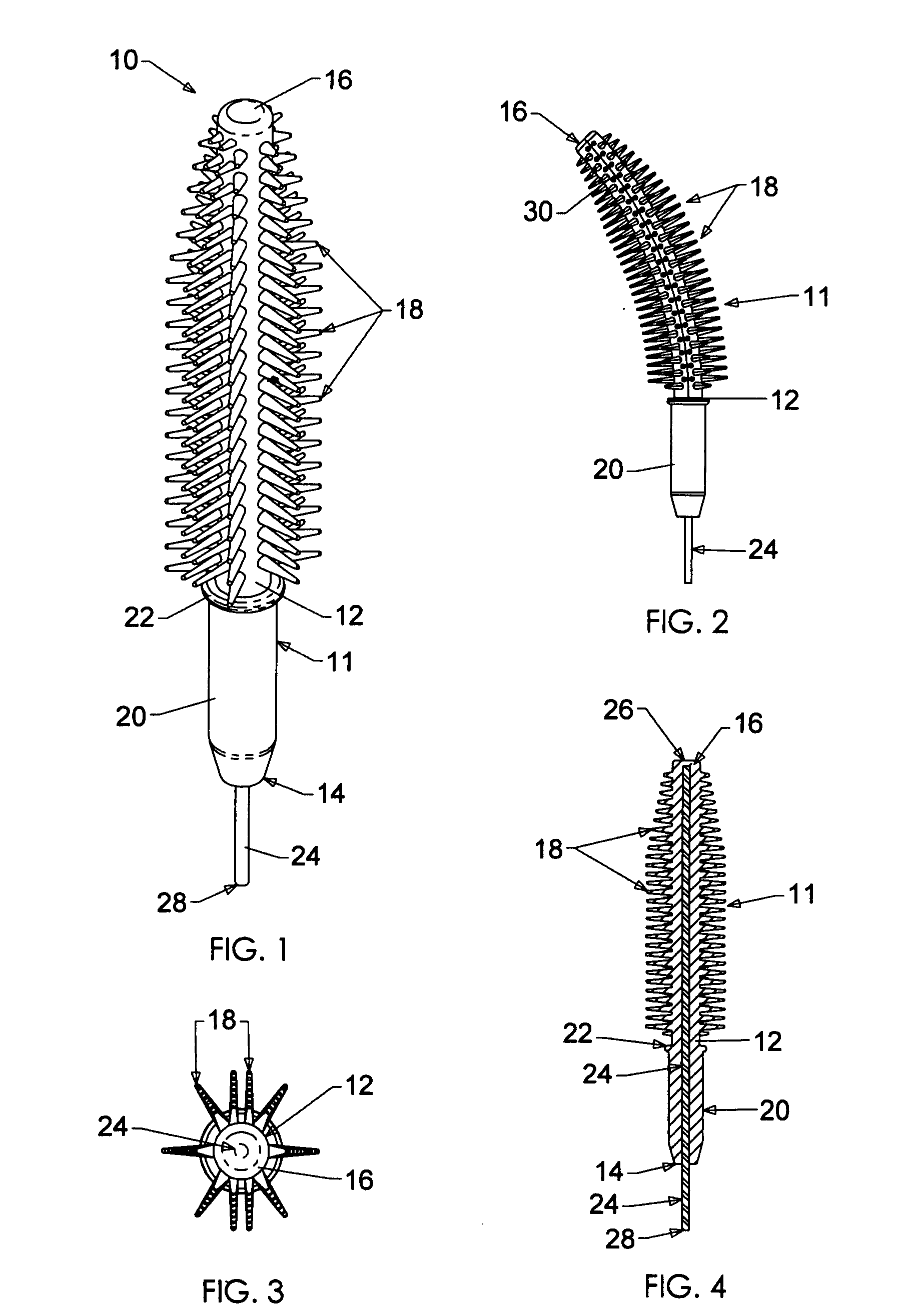
[0008]Very advantageously, the shape-retaining wire is a bendable, substantially non-resilient wire disposed within and extending lengthwise of the core for retaining a bend or curve manually imparted to the core. Thereby, the brush may be set in a desired curved or other bent configuration by simple manipulation, and the brush will sustain itself in the shape to which it is bent.
[0009]Also, another variation is to mold the brush with a more malleable wire core that allows the possibility that the curvature of the brush may be customized by the user.
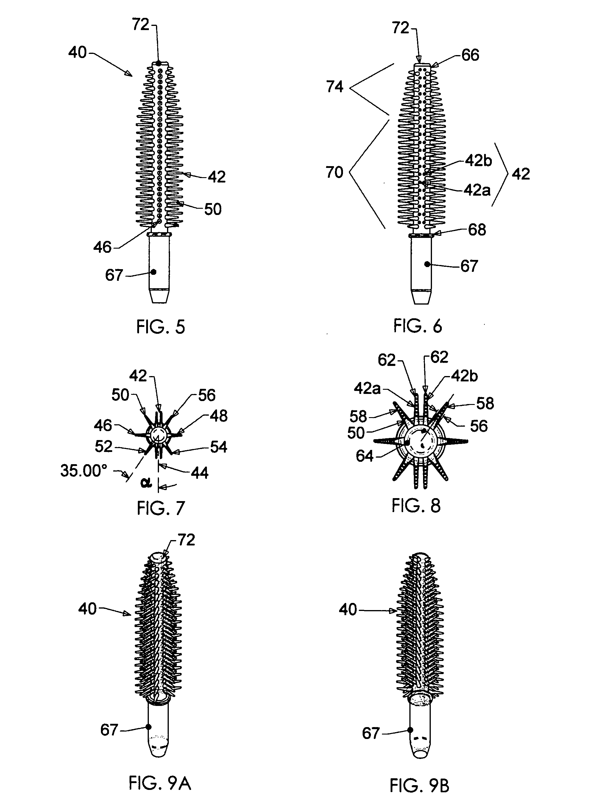
[0012]As an additional feature of the invention, the bristles may be arrayed in a plurality of rows extending lengthwise of the core and spaced laterally around the core periphery at unequal angular distances from each other, to achieve any of a virtually unlimited variety of configurations for such purposes as enhancing lash-thickening, lash-lengthening and / or lash-separation effects incident to mascara application.

Problems solved by technology

They are relatively costly, and there are only a limited number of suppliers.
To enable improved application, it would be beneficial to provide mascara brushes having structures other than uniformly distributed bristle arrays with simple cylindrical and / or conical envelopes of circular cross-section; but the diversity of possible configurations of twisted-in-wire brushes is restricted by the requirement to trim the bristles in order to achieve desired shapes, and the difficulty of forming and positioning cutters to effect such trimming.

Method used


Image

  • Molded plastic mascara brush
  • Molded plastic mascara brush
  • Molded plastic mascara brush

Examples


Embodiment Construction

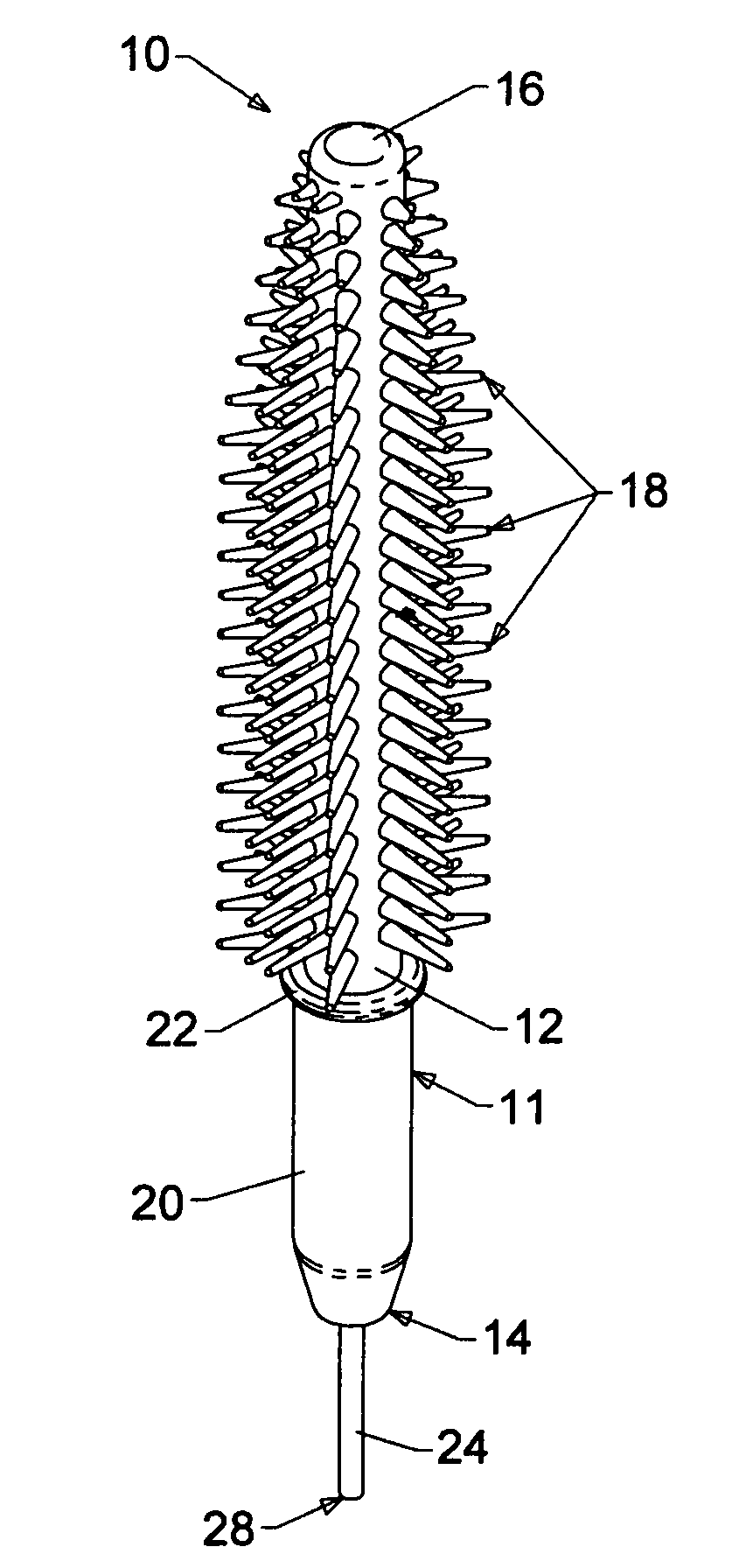
[0051]FIGS. 1-4 illustrate a mascara brush 10 embodying the present invention. This brush includes a flexible molded plastic body 11 comprising an elongated cylindrical core 12 with an initially rectilinear long geometric axis, a proximal end 14 and a distal end 16, and a multiplicity of bristles or fibers 18 projecting laterally outwardly from the core (transversely of the core axis) over a major portion of the length of the core from its distal end toward its proximal end. The proximal end portion of the core is formed as a shank 20, being bristle-free and (in this particular embodiment) slightly larger in diameter than the remainder of the core. A small flange 22 is provided between the shank and the bristle-bearing portion of the core in this embodiment.

[0052]In common with conventional mascara brushes, the brush 10 is designed to be mounted at its proximal end in a stem (not shown) of an applicator handle (also not shown) which includes a cap (not shown) for closing the neck of...


PUM


Abstract

A molded plastic mascara brush having an elongated flexible core with multiple bristles projecting radially therefrom, and a shape-sustaining wire extending longitudinally through the core. The wire may be bendable, enabling a desired curvature to be imparted to the brush. Additionally or alternatively, with the core and bristles molded integrally and at least some bristles disposed in rows extending lengthwise of the core, bristles may be spaced around the core at unequal angular distances, and / or bristles of at least one row may decrease progressively in length, and / or bristles may be disposed in tandem zones that differ from each other in bristle density, and / or some bristles may be disposed in rows and others of smaller diameter disposed in clusters.

Description

CROSS REFERENCE TO RELATED APPLICATIONS[0001]This application claims the benefit, under 35 U.S.C. §119(e), of U.S. provisional patent applications No. 60 / 830,719, filed Jul. 12, 2006, and No. 60 / 845,098, filed Sep. 15, 2006, the entire disclosures of both of which are incorporated herein by this reference.BACKGROUND OF THE INVENTION[0002]This invention relates to molded plastic brushes for applying mascara or the like to a user's eyelashes.[0003]Mascara brushes of the type commonly referred to as “twisted-in-wire” brushes are well known and widely used in the cosmetics industry. A twisted-in-wire mascara brush has an axially elongated twisted wire core with a multiplicity of fibers such as bristles clamped at their midpoints in the core and extending radially outwardly therefrom; the core is constituted of two lengths of wire, which may be initially separate or may be opposed legs of a single U-shaped wire, twisted together into a helix to hold the bristles between them. Typically, ...

Claims


Application Information

Patent Timeline
IPC IPC(8): A45D40/26A45D24/16A46B9/02
CPCA45D40/262A46B1/00A46B2200/106A46B9/028A46B2200/1053A46B9/021
Inventor MALVAR, MICHAELRIESS, FRANK A.SCHREPF, VOLKER
Owner ALBEA SERVICES SAS
Learn More